
User Manual


E-M-HF4-V1_22
Rotronic AG
Bassersdorf, Switzerland
Document code
Unit
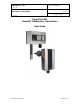
HygroFlex HF4 Humidity Temperature
Transmitters: User Guide
Instruction Manual
Document Type
Page
5 of 29
Document title
© 2009-2011; Rotronic AG E-M-HF4-V1_22
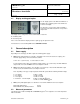
2.1 Display and keypad option
The LC display option for the HF43 and HF45 has a
backlight. The LC display option for the HF42 does
not have a backlight.
The upper line corresponds to relative humidity or
dew / frost point and the bottom line corresponds to
temperature.
The display can be configured to show a trend indicator on each line:
▲: increasing value
▼: decreasing value
In the event of an alarm the display shows the symbol [ ! ] to the right of the value.
For instructions see the following HW4 manual: E-M-HW4v3-F2-003.
3 General description
3.1 Power supply
Depending on the circuit type, the HF4 requires the following power supply:
a) HF42 (2-wire, loop powered): 10…28 VDC - depending on the load connected to the output(s). The
minimum supply voltage can be determined as follows:
V min = 10 V + (0.02 x Load*) *Load resistance in ohms.
For the maximum load of 500 , the minimum supply voltage is 10 + (0.02 x 500) = 20 VDC. With both
output circuits closed, the maximum current consumption is 40 mA.
b) HF43 (3-wire with analog outputs): 15 to 40 VDC (see note below) or 12 to 28 VAC. With both output
circuits closed, the maximum current consumption is 50 mA.
Note: depending on the type of output signal, the HF43 will operate with the following minimum voltage
0…1 V outputs: 5 VDC or 5 VAC
0…5 V outputs: 10 VDC or 8 VAC
0…10 V outputs: 15 VDC or 12 VAC
0…20 mA or 4 …20 mA outputs: 6 VDC or 5 VAC with 0 load
15 VDC or 12 VAC with 500 load
c) HF45 (3-wire) with digital outputs: 5 to 40 VDC or 12 to 28 VAC. Maximum current consumption:
Model with USB interface: 50 mA
Model with Ethernet (TCP/IP) interface: 300 mA
3.2 Measured parameters
The HF4 measures relative humidity with a ROTRONIC Hygromer
®
IN1 capacitive sensor and temperature
with a Pt100 RTD.