
Manual


E-M-HF5-V1_25
Rotronic AG
Bassersdorf, Switzerland
Document code
Unit
HygroFlex HF5 Humidity Temperature
Transmitters: User Guide
Instruction Manual
Document Type
Page
14 of 30
Document title
© 2009-2013; Rotronic AG E-M-HF5-V1_25
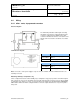
Mounting hardware
Method 1: The HF5 is supplied with 2 screws, 2 drywall anchors and two
rubber washers. The base of the enclosure has 2 screw-wells (see drawing)
that are normally closed at the bottom. Use the template provided with the HF5
to drill mounting holes in the wall and insert the drywall anchors. Place a
rubber washer on each screw. Insert a screw in each well and push to open
the bottom of the well.
Method 2: When a DIN-rail (35 mm / 1 3/8 “) is available use part AC5002 (not
included). This is a DIN-rail mounting kit consisting of 2 clamps that attach to
the back of the enclosure with the screws provided.
6 Electrical installation
6.1 General wiring guidelines
Power supply wiring
Heavy machinery and instrumentation should not share the same power supply wiring. If this cannot be
avoided, noise filters and surge protectors should be used. Most UPS devices have those features already
integrated.
General guidelines for signal cables
The following guidelines are derived from European Standard EN 50170 for the transmission of signals by
copper wires. When planning an installation, the rules provided by EN 50170 should be followed under
consideration of local circumstances to determine the position of machines and equipment.
All ROTRONIC products are tested for Electromagnetic Compatibility according to EMC Directive
2004/106/EG and following European standards:
- EN 61000-6-1: 2001, EN 61000-6-2: 2005
- EN 61000-6-3: 2005, EN 61000-6-4: 2001 + A11
Whenever the level of electromagnetic interference is expected to be high, both the instruments and signal
cables should be placed as far away as possible from the source of interference.
In general, signal cables should be installed in bundles or channels / conduits, separate from other cables as
indicated in the table below: