
Manual


E-M-HF5-V1_25
Rotronic AG
Bassersdorf, Switzerland
Document code
Unit
HygroFlex HF5 Humidity Temperature
Transmitters: User Guide
Instruction Manual
Document Type
Page
17 of 30
Document title
© 2009-2013; Rotronic AG E-M-HF5-V1_25
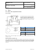
6.4.2 HF53: 3-wire transmitter
Electrical diagram for voltage outputs
The maximum permissible cable length can be
determined under consideration of the voltage drop
caused by the current flowing to the devices
connected to the unit. The voltage drop in the cable
depends both on cable resistance and on the
equivalent resistance of the devices connected in
parallel to the unit. The total resistance connected to
each unit output should be at least 1000 ohms.
Cable resistance should not be more than 1/1000 of
the load resistance.
Electrical diagram for current outputs
The maximum permissible cable length, connecting
the unit to other devices, is determined by the total
resistance resulting from the addition of the cable
resistance and that of the devices connected in series
with the unit. This resistance should not exceed 500
ohms.
Terminal block diagram (analog outputs only)
Type D and W (horizontal mount)
Terminals
Description
K1-1: GND
Power supply (-) or neutral
(tied with other GND)
K1-2: V+
Power supply: 15…40 VDC (+)
or 12…28 VAC (Phase)
K1-3: -►
Protective ground (see note below)
Terminals
Description
K2-4: GND
Ground (tied with other GND)
K2-3: GND
Ground (tied with other GND)
K2-2: OUT2
Temperature output (+)
K2-1: OUT1
Relative humidity or dew point (+)