
Manual


E-M-HF5-V1_25
Rotronic AG
Bassersdorf, Switzerland
Document code
Unit
HygroFlex HF5 Humidity Temperature
Transmitters: User Guide
Instruction Manual
Document Type
Page
20 of 30
Document title
© 2009-2013; Rotronic AG E-M-HF5-V1_25
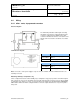
6.4.3 HF55: digital output
Connectors and terminal block diagram
Notes:
Terminal K1-3: this terminal (protective or earth ground) is not tied with GND. If so desired, K1-3 can be tied
with GND by closing a solder pad on the PCB
Terminal block K3 (RS-485): with the exception of models with the galvanically isolated power supply option,
terminals K3-1 and K3-2 can be used to power the HF55 from a 15 to 24 VDC power supply connected to the
RS-485 main data line. In this case, do not use terminals K1-1 and pin K1-2 (normally used to power the
HF55).
WARNING: Connecting a device to an active Ethernet network can disrupt communications on the network.
Before connecting the HF5, make sure that it is properly configured for your network.
6.4.4 Grounding (all models)
We generally recommend grounding the (-) side of the power supply, especially if the electronics will be
subjected to a low humidity environment (35 %RH or less).
Terminals
Description
K1-1: GND
Power supply (-) or neutral
(tied with other GND)
K1-2: V+
Power supply: 5…40 VDC (+)
or 12…28 VAC (Phase)
K1-3: -►
Protective ground (see note below)
Terminals
Description
K3-4: D-
RS-485 Bi-directional
TX- / RX -
K3-3: D+
RS-485 Bi-directional
TX+ / RX +
K3-2: GND
Ground / Power supply (-)
K3-1: PWR
DC (+) 15…24 VDC (+)
(optional, see note below)