
Manual

E-M-HF5-V1_25
Rotronic AG
Bassersdorf, Switzerland
Document code
Unit
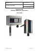
HygroFlex HF5 Humidity Temperature
Transmitters: User Guide
Instruction Manual
Document Type
Page
5 of 30
Document title
© 2009-2013; Rotronic AG E-M-HF5-V1_25
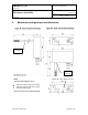
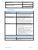
2.1 Display and keypad option
The LC display option for the HF53 and HF55 has a
backlight. The LC display option for the HF52 does
not have a backlight.
The upper line corresponds to relative humidity or
dew / frost point and the bottom line corresponds to
temperature.
The display can be configured to show a trend indicator on each line:
▲: increasing value
▼: decreasing value
In the event of an alarm the display shows the symbol [ ! ] to the right of the value.
For instructions see the following HW4 manual: E-M-HW4v3-F2-005.
3 General description
3.1 Power supply options
Depending on the circuit type, the HF5 requires the following power supply:
a) HF52 (2-wire, loop powered): 10…28 VDC - depending on the load connected to the output(s). The
minimum supply voltage can be determined as follows:
V min = 10 V + (0.02 x Load*) *Load resistance in ohms.
For the maximum load of 500 , the minimum supply voltage is 10 + (0.02 x 500) = 20 VDC. With both
output circuits closed, the maximum current consumption is 40 mA.
b) HF53 (3-wire with analog outputs):
- Option 1, standard power supply: 15 to 40 VDC or 12 to 28 VAC
- Option 2: galvanically isolated power supply: 9 to 36 VDC or 7 to 24 VAC
With both output circuits closed, the typical current consumption is 100 mA.
Please verify the product identification label to determine which power supply option is installed on your
transmitter.
c) HF55 (3-wire) with digital outputs:
- Option 1, standard power supply: 5 to 40 VDC or 12 to 28 VAC
- Option 2: galvanically isolated power supply: 9 to 36 VDC or 7 to 24 VAC
- Option 3: PoE (power over Ethernet). This option is not available with units equipped with a RS-485
interface. Any unit equipped with the PoE option can be powered only via a LAN.