
Manual

E-M-HF5-V1_25
Rotronic AG
Bassersdorf, Switzerland
Document code
Unit
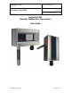
HygroFlex HF5 Humidity Temperature
Transmitters: User Guide
Instruction Manual
Document Type
Page
6 of 30
Document title
© 2009-2013; Rotronic AG E-M-HF5-V1_25
Tyical current consumption:
Model with USB interface : 100 mA
Model with Ethernet (TCP/IP) interface: 300 mA
3.2 Measured parameters
The HygroClip 2 probe used with the HF5 transmitter measures relative humidity with a ROTRONIC
Hygromer
®
IN1 capacitive sensor and temperature with a Pt100 RTD.
3.3 Calculated parameters
Using the ROTRONIC HW4 software, the HF5 can be configured by the user to calculate one of the following
parameters:
o Dew point (Dp) above and below freezing
o Frost point (Fp) below freezing and dew point above freezing
o Wet bulb temperature (Tw)
o Enthalpy (H)
o Vapor concentration (Dv)
o Specific humidity (Q)
o Mixing ratio by weight (R)
o Vapor concentration at saturation (Dvs)
o Vapor partial pressure (E)
o Vapor saturation pressure (Ew)
Note: some of the above parameters depend on the value of the barometric pressure. Using the ROTRONIC
HW4 software, a fixed barometric pressure value can be specified. For instructions see the following HW4
manual: E-M-HW4v3-F2-005
3.4 Analog output signals (HF52 and HF53)
HF52 and HF53
With the ROTRONIC HW4 software any of the two analog output signals can be made to correspond to one of
the following:
Relative humidity
Temperature
Calculated parameter
Any output can also be disabled.
The scale of each analog output can be set within the numerical limits of -999.99 and 9999.99. The D/A
converters used to generate the analog output signals feature a 16-bit resolution.
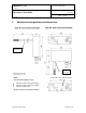
HF53
The type of output signal can be changed by means of jumpers to one of the following: 0…20 mA, 4…20 mA,
0…1V, 0…5V or 0…10V (see 5.2). Both output signals are automatically configured with the same signal type.
No adjustment is required after changing the type of output signal.