
User Manual


E-M-HyLabC1-V1
Rotronic AG
Bassersdorf, Switzerland
Document code Unit
HygroLab C1 bench-top indicator:
User Guide
Instruction Manual
Document Type
Page
4 of 28
Document title
© 2011; Rotronic AG E-M-HyLabC1-V1
2 Gener al de s cr iption
2.1 Configuration softw are
Most of the HygroLab C1 setti ngs can be conf igur ed directly from the keypad. However, some of the settings
and access to some of the functions requires connecting the HygroLab C1 to a PC running the HW4 software
version 3.1 or higher, using either USB or Ethernet. For instructions see the following HW4 manual: E-M-
HW4v3-F2-019
2.2 Power suppl y
The HygroLab C1 requires the power adapter model AC1211 (100…240 VAC – 12 VDC, 200 mA).
As an alternative, the HygroLab C1 can also be powered via the USB port (no power adapter - current draw:
about 70 mA). In this case, the Ethernet port is inactive and cannot be used.
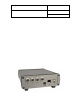
2.3 Probe inputs
The HygroLab C1 has 4 probe inputs designed for use with all HygroClip 2 digital probes with the standard
UART interface (see also Back panel and digital interface options).
Pin-Out Diagram
2.4 Measured parameters
The HygroClip 2 probe measures relative humidity with a ROTRONIC Hygromer® IN1 capacitive sensor and
temperature with a Pt100 RTD.
2.5 Calculated parameters
The HygroLab C1 can calcu lat e any of the following parameters based on the humidity and temperature
values measured by the probe (to select the calculated parameter, use either the keypad or the HW4 software
> Device Manager):
o Dew point (Dp) above and below freezing
o Frost point (Fp) below freezing and dew point above freezing
o Wet bulb temperature (Tw)
o Enthalpy (H)
o Vapor concentr atio n (Dv )
o Specific humidity (Q)
o Mixing ratio by weight (R)
o Vapor concentr atio n at satur ati on (Dv s)
o Vapor partial pressure (E)
o Vapor saturation pressure (Ew)
1: RXD (UART- digital probe)
2: GND (digital and pow er)
3: V+: 3.3 VDC nominal
4: Not used
5: Not used
6: Not used
7: TXD (UART – digital probe)