
Manual


E-M-HM-V1_12
Rotronic AG
Bassersdorf, Switzerland
Document code Unit
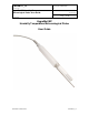
HygroMet MP Humidity Temperature
Meteorological Probe: User Guide
Instruction Manual
Document Type
Page
5 of 20
Document title
© 2009-2011; Rotronic AG E-M-HM-V1_12
3 General description
3.1 Power supply
Depending on the circuit type, the HygroMet MP requires the following power supply:
a) 2-wire, loop powered version: 10…28 VDC - depending on the load connected to the output(s). The
minimum supply voltage can be determined as follows:
V min = 10 V + (0.02 x Load*) *Load resistance in ohms.
For the maximum load of 500 Ω, the minimum supply voltage is 10 + (0.02 x 500) = 20 VDC. With both
output circuits closed, the maximum current consumption is 40 mA.
b) 3-wire version: 15 to 24 VDC. With both output circuits closed, the maximum current consumption is 50
mA.
Depending on the type of analog output signal, the minimum supply voltage can be reduced as follows:
0…1 V outputs: 5 VDC minimum
0…5 V outputs: 10 VDC minimum
3.2 Measured parameters
The HygroClip HC2-S3 probe used with the HygroMet MP measures relative humidity with a ROTRONIC
Hygromer
®
IN1 capacitive sensor and temperature with a Pt100 RTD.
3.3 Calculated parameters
Using the ROTRONIC HW4 software, the HygroMet MP can be configured by the user to calculate one of the
following parameters:
o Dew point (Dp) above and below freezing
o Frost point (Fp) below freezing and dew point above freezing
o Wet bulb temperature (Tw)
o Enthalpy (H)
o Vapor concentration (Dv)
o Specific humidity (Q)
o Mixing ratio by weight (R)
o Vapor concentration at saturation (Dvs)
o Vapor partial pressure (E)
o Vapor saturation pressure (Ew)
Note: some of the above parameters depend on the value of the barometric pressure. Using the ROTRONIC
HW4 software, a fixed barometric pressure value can be specified. For instructions see the following HW4
manual: E-M-HW4v3-F2-014