
Product Manual


Page 4 of 6
LOW-PROFILE STEEL OIL DRAIN USE AND CARE
• Do not modify the LOW-PROFILE steel oil drain in any way. Unauthorized modification may
impair the function and/or safety and could affect the life of the equipment. There are specific
applications for which the low-profile steel oil drain was designed.
• Always check for damaged or worn out parts before using the LOW-PROFILE steel oil
drain. Broken parts will affect the low-profile steel oil drain operation. Replace or repair damaged
or worn parts immediately.
• Do not exceed the LOW-PROFILE steel oil drain load capacity.
• Distribute the load evenly. Uneven loads may cause the low-profile steel oil drain to tip,
resulting in personal injury to the operator or others.
• Use the LOW-PROFILE steel oil drain on flat and level surfaces capable of supporting the
low-profile steel oil drain and its maximum load. Pulling or pushing a load on a slanted or uneven
surface can result in loss of control.
• Store idle LOW-PROFILE steel oil drain. When low-profile steel oil drain is not in use, store it in
a secure place out of the reach of children. Inspect it for good working condition prior to storage
and before re-use.
• Do not DRAIN gasoline, caustic, or flammable products.
WARNINGS FOR ELECTRIC PUMP
1. If the plug on the pump is damaged, replace by a qualified service technician.
2. To prevent serious injury from accidental operation: Disconnect the Pump from its 110 Volt
connection before performing any inspection, maintenance, or cleaning procedures.
3. To prevent serious injury from pump failure: Do not use damaged equipment. If abnormal noise
or vibration occurs, have the problem corrected before further use.
4. Never smoke near the Pump or use the Pump near an open flame. Fire could result.
5. Designate a work area that is clean and well-lit. The work area must not allow access by children
or pets to prevent distraction or injury.
6. Route the cord along a safe route to reach the work area without creating a tripping hazard or
exposing the cables to possible damage. The cord must reach the work area with enough extra
length to allow free movement while working.
7. There must not be hazardous objects, such as utility lines or foreign objects, nearby that will
present a hazard while working.
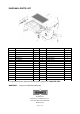
ASSEMBLY
See parts diagram for reference during assembly
1. Attach the Wheel (#26) together with Bearing (#24) to the wheel axle under the back of the
Reservoir (#19) , secure with Bolt (#23), Washers (#15), Retaining rings (#25) and Lock Nut
(#27). Be sure the wheel can spin freely.
2. Attach the Caster (#12) to the bracket at the front of the Reservoir (#19); secure with Washer
(#15) , Spring Washer (#14) and Nut (#13).
3. Connect one end of Short Hose (#10) to Hose Fitting (#11) under the Reservoir(#19), and
another end to Hose Fitting (#28) under the Pump (#9); secure them with Hose Clamps (#6).
4. Connect Long Hose (#3) to Hose Fitting (#7) on top of the Pump (#9), Secure with Hose Clamps
(#6).
5. Attach the Handle Seater (#22) on the top front of the Reservoir (#19), secure with Bolt (#20),