Air-Operated Double-Diaphragm Pump Owner’s Manual WARNING: Read carefully and understand all ASSEMBLY AND OPERATION INSTRUCTIONS before operating. Failure to follow the safety rules and other basic safety precautions may result in serious personal injury.
Thank you very much for choosing a Roughneck™ product! For future reference, please complete the owner’s record below: Serial Number/Lot Date Code: ________________________________ Purchase Date: ____________________________________________ Save the receipt, warranty, and this manual. It is important that you read the entire manual to become familiar with this product before you begin using it. This pump is designed for certain applications only.
Table of Contents Intended Use .......................................................................................................................................... 4 Technical Specifications ...................................................................................................................... 4 Important Safety Information ............................................................................................................... 5 Specific Operation Warnings .......................
Intended Use The Roughneck Air-Operated Double-Diaphragm Pump is widely used in various industries, such as petroleum, metallurgy, mining, coating material, printing, paper-making, electronic, textile, furnishing, environmental protection, water treatment, and automotive. Technical Specifications Model Inlet/Outlet Air Inlet Flow Rate Max. Head Max. Pressure Max. Suction Height Max.
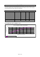
AIR CONSUMPTION CHART FOR MODEL: #58240 Air consumption chart for #17150500&17150600 Air Consumption (m3/h) 12 11 10 9 8 7 6 2 3 4 5 5.8 7 7.5 Outlet Pressure (Bar) Air Consumption (m3/h) AIR CONSUMPTION CHART FOR MODEL: #58239 & #58241 Air consumption chart for #17150501&17150601 Air Consumption (m3/h) 12 11 10 9 8 7 6 2.2 3 4 5.2 6 7 7.5 Outlet Pressure (Bar) Air Consumption (m3/h) Important Safety Information ⚠WARNING Read and understand all instructions.
product will be safer and do a better job at the capacity for which it was intended. DO NOT use this equipment for a purpose for which it was not intended. Industrial or commercial applications must follow OSHA requirements. ⚠WARNING WORK AREA SAFETY Inspect the work area before each use. Keep work area clean, dry, free of clutter, and well-lit. Cluttered, wet, or dark work areas can result in injury.
PUMP USE AND CARE Do not force the pump. Products are safer and do a better job when used in the manner for which they are designed. Plan your work, and use the correct product for the job. Check for damaged parts before each use. Carefully check that the product will operate properly and perform its intended function. Replace damaged or worn parts immediately. Never operate the product with a damaged part. Do not use a product with a malfunctioning switch.
After grounding, periodically verify continuity of electrical path to ground. Test with an ohmmeter from each component (e.g., hoses, pump, clamps, container, spray gun, etc.) to ground to insure continuity. Ohmmeter should show 100 ohms or less. Pump exhaust may contain contaminants which can cause severe injury. Pipe exhaust away from work area and personnel. In the event of a diaphragm rupture material can be forced out of the air exhaust muffler.
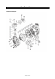
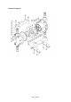
Main Parts of Product #58242 Parts Diagram Page 9 of 25
#58240 Parts Diagram Page 10 of 25
#58239 & #58241 Parts Diagram Page 11 of 25
Assembly Instructions • • • The diaphragm pump offers high volume delivery even at low air pressure. Air-operated double diaphragm pumps utilize a pressure differential in the air chambers to alternately create suction and positive fluid pressure in the fluid chambers. The ball check insures a positive flow of fluid. Pump cycling will begin as air pressure is applied and it will continue to pump and keep up with the demand.
Consult local building codes and electrical codes for specific grounding requirements. After grounding, periodically verify continuity of electrical path to ground. Test with an ohmmeter from each component (e.g., hoses, pump, clamps, container, spray gun, etc.) to ground to insure continuity. Ohmmeter should show 100 ohms or less. In the event of a diaphragm rupture material can be forced out of the air exhaust muffler. Do not use the pump for the structural support of the piping system.
Appendix 3 Scope of Chemical Usage (SAVE).
Page 15 of 25
After Each Use ⚠WARNING Store idle equipment. When not in use, tools and equipment should be stored in a dry location to inhibit rust. Maintenance ⚠WARNING Provide a clean work surface to protect sensitive internal moving parts from contamination from dirt and foreign matter during service disassembly and reassembly. Keep good records of service activity and include pump in preventive maintenance program.
Parts Diagram #58242 Parts Diagram Page 17 of 25
#58240 Parts Diagram Page 18 of 25
#58239 & #58241 Parts Diagram Page 19 of 25
AIR MOTOR SECTION No. Description Qty. No. Description Qty. 1 Hex-bolt M6X20 4 11 Washer 2 2 Press board 1 12 Major Valve 1 3 Seal for press board 1 13 O-ring 9.93X2.62 5 4 Spacer 4 14 Sleeve 1 5 Spacer 5 15 O-ring 20.35X1.78 3 6 Spacer 2 16 Retaining Ring 25 1 7 O-ring 20.35X1.78 6 17 O-ring 7.1X2.65 2 8 Hex bolt M5X12 8 18 Pilot Valve 1 9 Gasket 2 19 O-ring 6.86X1.
Parts List #58242 Parts List Parts 1 2 3 4 5 6 7 8 Description Hex-bolt M8×70 Discharge Manifold O-ring Valve Cover Valve Ball Valve Seat Liquid Chamber Hex-bolt M8X50 Quantity 8 2 8 4 4 4 2 20 9 Liquid Chamber Plate 2 10 Diaphragm 2 11 Air Chamber Plate 2 13 Connecting Shaft 1 14 Screw 12 15 Air Chamber 2 16 Screw 28 17 O-ring 2 18 Air Motor Assembly 1 19 Bracket 2 Parts 1 Description Hex-bolt M8×55 Quantity 4 2 Discharge Manifold 1 3 Valve cover 1 4 Valve Ball 4
Parts 16 Description Connecting Shaft Quantity 3 17 Air Chamber 1 18 O-ring 94.92X2.62 2 19 Hex-bolt M8 1 20 Screw M5X8 5 21 Washer 1 22 Air Motor Assembly 2 23 straight pin 1 #58239 & #58241 Parts List Parts 1 Description Hex-bolt M8×55 Quantity 8 2 Discharge Manifold 2 3 Valve cover 4 4 Valve Ball 4 5 Valve Seat 4 6 O-ring 28.24x2.
Replacement Parts For replacement parts and technical questions, please call Customer Service at 1-800-222-5381. Not all product components are available for replacement. The illustrations provided are a convenient reference to the location and position of parts in the assembly sequence. When ordering parts, the following information will be required: item description, item model number, item serial number/item lot date code, and the replacement part reference number.
Limited Warranty Northern Tool and Equipment Company, Inc. ("We'' or "Us'') warrants to the original purchaser only ("You'' or "Your") that the Roughneck product purchased will be free from material defects in both materials and workmanship, normal wear and tear excepted, for a period of one year from date of purchase. The foregoing warranty is valid only if the installation and use of the product is strictly in accordance with product instructions.
Distributed by: Northern Tool & Equipment Company, Inc. Burnsville, Minnesota 55306 www.northerntool.