OIL TRANSFER KIT OWNER’S MANUAL WARNING: Read carefully and understand all INSTRUCTIONS before operating. Failure to follow the safety rules and other basic safety precautions may result in serious personal injury.
Thank you very much for choosing a Roughneck™ Product! For future reference, please complete the owner’s record below: Model: _______________ Purchase Date: _______________ Save the receipt, warranty and these instructions. It is important that you read the entire manual to become familiar with this product before you begin using it. This machine is designed for certain applications only. The distributor cannot be responsible for issues arising from modification.
GENERAL SAFETY REGULATIONS WARNING: Read and understand all instructions. WARNING: The warnings, cautions, and instructions discussed in this instruction manual cannot cover all possible conditions or situations that could occur. It must be understood by the operator that common sense and caution are factors that cannot be built into this product, but must be supplied by the operator. 1. Keep the work area clean and dry. Damp or wet work areas can result in injury. 2. Keep children away from work area.
Do not misuse this equipment to pump fluids and solvents which may cause damage to the wetted parts of the equipment. Refer to instructions of the manufacturers of the fluids and solvents. Handle hoses carefully. Do not pull on hoses to move equipment. Route hoses away from traffic areas, sharp edges, moving parts, and hot surfaces. Wear heat insulated gloves when operating the pump. Do not move or lift pressurized equipment.
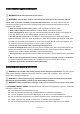
INSTALLATION Typical installation refers to Fig.1. Fig. 1 NOTE: The above typical installation is only for reference. It may be different from your actual system design. WARNING: If this is a new installation, or if the oil in the lines is contaminated, flush the lines before you install the kit. No impurities or contaminant are allowed to enter the kit. WARNING: To reduce the risk of serious injury, the pressure release should be concerned.
1. Ground Screw 2. Ground Wire Fig.1 Ground the pump Air and fluid hoses: Make sure they are effectively grounded. Air compressor: Follow the manufacturer's instruction to ground it. Control valve: Use proper grounding wire to connect it to the pump. Always keep the metal part of the control valve connected with the grounding equipment. Oil Barrel: Use a barrel that can meet the local standard and ground it properly.
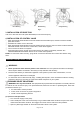
Floor Mounting Wall Mounting Ceiling Mounting Fig. 2 3. INSTALLATION OF DROP TRAY Use one or two bolts and nuts (NOT INCLUDED) to secure the drop tray. 4. INSTALLATION OF CONTROL VALVE ①. Apply appropriate thread sealant around the male thread of flexible spout, and then screw the flexible spout to the meter. ②. Assemble the rubber cover to the meter. ③.
④. Leave the drain valve open until you are ready to pressurize the system. (2) Clean the obstruction in the oil system, when any of the following cases occurs: ①. Problem on control valve, flexible hose, rigid tube or manual/auto tip. ②. Pressure can not be relieved completely after above procedures are done. ③. It takes more than 5 seconds to relieve the pressure thoroughly. 2. OPERATION WARNING: Follow the instructions in PRESSURE RELIEF PROCEDURE before each operation. ①.
Fig. 3 . Replace and tighten the nuts and washers. . Tighten the drive spring by turning the spool two or three circles and engage the latch pawl. . Pull the hose through the roller opening in the guide arm and replace the stopper. 4. OPERATION OF CONTROL VALVE (1) LCD DISPLAY INDICATIONS: See the following displaying illustration of the LCD panel. Fig. 4 LCD panel displays region ①. Partial register Measurement exceeds the maximum value will become zero and re-measure. ②.
①. Move the flashing display to Zone ② by pressing “MENU”, then press “RESET” to choose measurement unit; ②. Press “MENU” over 3 seconds to exit the setting mode. B. Resetting the accumulated total Press “MENU” for 10 seconds, the accumulated total will be reset to be “0”. C. Displaying current correction factor Press “MENU” and “RESET” simultaneously and hold for 2 seconds. The display shows the correction factor. (3) CALIBRATION PROCEDURE A. Procedure for entering the correction factor directly ①.
Continuous air exhaust Erratic pump operation Pump operates, but output low Leaking from muffler plates Oil control valve: Problem Exhausted fluid supply Refill and re-prime or flush Worn or damaged air motor gasket or seal Assess wear or damage, and service air motor Exhausted fluid supply Refill and re-prime or flush Worn pump seals Replace pump seals Damaged hose Worn piston seal Worn seals Clogged fluid line, hose, valve, or other accessory Replace hose Replace piston seal Replace seals Worn
MAINTENANCE CAUTION: Remove all tension before servicing. Hazards or unsafe practices MAY result in minor personal injury, product or property damage. WARNING: Before performing any service, always disconnect and lock out compressed air or fluid, and remove all spring tension. Hazards or unsafe practices COULD result in severe personal injury or death. WARNING: User servicing of the reel is limited to replacing input/output hoses only. Refer all other repairs to an authorized service person.
②. Store it out of the reach of children. ③. Always keep the pump at least 4 feet away from any heat source. DIAGRAMS AND PARTS LIST 8 1 2 11 10 5 12 9 6 13 3 4 14 7 Part No. 1 Description Oil pump Qty. 1 Part No. 8 Description Rigid suction hose Qty. 1 2 3 Hose reel Oil Control Valve 1 1 9 10 Pump adapter 3/4in. to 1/2in.
1. 17130503 Oil pump Part No. Description Qty. Part No. Description Qty.
17* O-ring 1 44 Bolt 12 18 21 Oil inlet valve Piston shaft 1 1 45 46 Bolt Adjustable nut 1 2 22 Left silencer 1 47 Nut 2 23 24 Transfer slipcover Shaft 1 1 48 49 Bung adapter Label 1 2 25 Screw 6 50* O-ring 1 26* 27 O-ring Piston 1 1 51 52 Steel ball Steel ball 1 1 Part No. 2* Description Spring piece Qty. 2 Part No. 26* Description O-ring Qty.
4 Bolt 5 Bracket arm 6 Washer 7 Ratchet 8 Washer 9 Lock washer 10 Click pulley 11 Nut 12 Lock washer 13 Washer 14 Shaft 15 Key 16 Guide sub-plate 17 Drum 18 Roller axle 19 Roller 20 Roller 21 Roller axle 22 Guide plate 3. 18123522 Digital Oil Control Valve Part No. Description 9 1 1 1 1 1 1 8 2 4 1 1 1 1 2 2 2 2 1 26 27 28 29 30 31 32 35 36 37 38 39 40 41 43 44 45 46 47 Qty. Part No.
1-5* 1-6 1-7* O-ring Screw Washer, flat 2 2 2 3-9* 3-10 3-11 O-ring Seat Battery cover 1 1 11 1-8 1-9 Cam Rod 1 1 3-12 3-13* Spring Battery 1 1 1-10* 1-11 Seat Washer 1 1 3-14 3-15 Screw Shaft 2 2 1-12 Spring 1 3-16 Oval Gear 2 1-13* Filter 1 3-17 Magnetic Rod 2 Adapter 1 3-18 Bolt 8 3-1* O-ring 1 3-19* Waterproof protector 2 3-2 3-3 Meter Holder Meter Cover 1 1 3-20* 3-21 Seal washer Washer 4 4 3-4 Rubber Protector 1 4 Nozzle with tip 1 Qty. Part No.