
Product Manual


Page 9 of 16
①. Move the flashing display to Zone ② by pressing “MENU”, then press “RESET” to choose measurement
unit;
②. Press “MENU” over 3 seconds to exit the setting mode.
B. Resetting the accumulated total
Press “MENU” for 10 seconds, the accumulated total will be reset to be “0”.
C. Displaying current correction factor
Press “MENU” and “RESET” simultaneously and hold for 2 seconds. The display shows the correction factor.
(3) CALIBRATION PROCEDURE
A. Procedure for entering the correction factor directly
①. Wait for the control valve to go to standby.
②. Press the “MENU” key. Keep it pressed until the digit flashes in Zone ①. Press the “RESET” key to
choose the right digit from 0 to 9. Press the “MENU” key to go the next digit so that the Actual Value can
be input.
③. Make sure the correction factor is right and then press the “MENU” key. Keep it pressed until calibration is
finished and the factor is saved. The control valve will then return to standby.
B. Modify the correction factor in field
①. Press the “RESET” for 1 second, Zone displays “0.00”.
②. Start dispensing into a measuring glass.
③. Stop dispensing when over 5 liters of volume is reached, then check the actual dispensed value. The
volume that is displayed on the LCD is the Display Value, not the Actual Value.
④. Press the “MENU” key. Keep it pressed until the digit flashes in Zone ①. Then press the RESET key to
choose the right digit from 0 to 9. Press the “MENU” key to go the next digit so that the Actual Value can
be input.
⑤. Make sure the Actual Value is input right and then press the “MENU” key. Keep it pressed until calibration
is finished and the factor is saved. The meter will then return to standby.
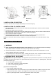
(4) BATTERY REPLACEMENT
If Voltage is too low, low-power alarm device will be activated and light flashes in Zone ④.
When the LCD panel displays nothing or light flashes in Zone ④, the battery should be replaced. Follow the
steps below to replace new battery.
①. Open the battery cover (part# 3-11) with a flat screwdriver.
②. Remove the old battery. Discard the battery in accordance with local laws and ordinances.
③. Insert a 3.6V ER14250 battery into the battery compartment. Install the battery according to the direction
of polarity “+” & “-” indicated and insert the end of anode “+” first.
④. Place back the battery cover (part# 3-11).
TROUBLE SHOOTING
WARNING: Relieve pressure before you check or service any system equipment.
Oil pump:
Problem
Possible Cause
Corrective Action
Inadequate air supply pressure or
restricted air lines
Increase air supply and/or
clear restriction
Closed or clogged control valves
Open and/or clean
Clogged fluid line, hose, valve, or
other accessory
Relieve pressure
Clear obstruction
Pumps fails to
operate
Damaged air motor
Assess damage, and service air
motor