
Mowers Lawn Mower Owners Manual


Powered Walk Behind Mower - CE Part No. 04016218 Rev F © Copyright 10/2005
™
4
Rover Mowers Ltd
ABN 11 000 257 303
ENGLISH
OPERATION (Continued)
Installing the Grass catcher
• Raise the rear flap of the mower.
• Grasp the grass catcher by the top handle and position the grass catcher against the rear of the mower (refer figure 7).
• Lower the rear flap so that the back edge of the flap hooks over the matching lip on the grass catcher.
Removing the Grass catcher
• Grasp the grass catcher top handle and lift up.
• Raise the rear flap of the mower to release grass catcher.
• Lift the grass catcher clear of the mower and lower the rear flap.
MULCH PLUG
• Refer to the separate Mulch ‘n’ Catch Owners Manual.
GRASS DEFLECTOR
• Refer to the separate Grass Deflector Owners Manual.
ADJUSTING THE CUT HEIGHT
• When setting the cut height stand to the rear of the machine with your feet well clear of
the cutting blades.
WARNING
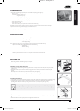
• Grasp the height of cut lever (A) and apply an outward pressure to release the lever from the rack (B) (refer figure 8).
• Move the lever (while holding out) to the required height of cut position and engage the lever in the rack.
• Pushing the lever forward and down raises the cut height and vice versa.
It is advisable to start the mower in the high cut position and gradually drop the height notch by notch until the desired height is
achieved. Starting too low will leave a low spot in the lawn.
ENGINE
NOTE: The mowers covered in this manual have various engine types from various manufacturers. Included in the Mower Kit is an engine manual specific to each mower
which provides the details for the engine’s operation. Please refer to the engine manufacturer’s manual for precise instructions.
Starting the Engine
• The engine safety precautions, oil and fuel recommendations, operation instructions, adjustments and maintenance is covered in the
engine manufacturer’s manual which is included in the mower kit. Please refer to and adhere to these recommendations.
• If you do not have the engine manufacturer’s manual please refer to the nearest engine manufacturer’s representative for a
replacement copy.
• The engine is packed without oil or fuel. Please add these as per the engine manufacturer’s recommendations before attempting
to start the engine.
• If fitted with the Powerstart option activate the operator presence control lever (to release the blade brake) before attempting
to crank the engine.
CAUTION
• Refer to the “Warning” notes at the beginning of the “Operation” section.
• Start the mower on a clear level surface.
• Keep your fingers, toes and bystanders clear when starting or operating the engine.
• If fitted with the Powerstart option, always remove the key from the ignition switch and keep in a safe place to prevent unauthorised
cranking of the engine.
WARNING
• Refer to the engine manufacturer’s manual for the starting procedure, remembering to activate the operator presence control lever before cranking the engine.
• If fitted with the Powerstart option, insert the key into the ignition switch then follow the instructions in the engine manufacturer’s manual.
The Rover throttle control uses symbols to indicate the throttle function at various throttle positions:
O (off), (slow speed), (fast speed), (engine choke)
These positions align with settings required in the engine manufacturer’s manual.
The Rover Powerstart option can be started with an ignition key which is fitted to the handle bar. The switch plate uses symbols to
indicate the key function at various positions and refers to the state of the starter motor:
O (off), I (on/start). These positions align with the settings required in the engine manufacturer’s manual.
Stopping the Engine
• Refer to the engine manufacturer’s manual for stopping procedure.
• If fitted with the Powerstart option remove the ignition key and store in a safe place after use.
7
8
Powered Walk Behind A4 CE English.indd 30/11/02, 9:51 PM7
3
Rover Mowers Ltd
ABN 11 000 257 303
ENGLISH
SETTING UP (Continued)
REMOVING THE PACKAGING TIES FROM THE CONTROL HANDLES
Remove and discard the packaging ties clamping the blade brake and self propelled drive
control bale to the handle bar before attempting to start the mower (refer figure 5).
WARNING
• Unfold the handlebars and lock in the erect position (refer to the “Folding the Handlebar” section).
• Remove the packaging ties (refer figure 5).
ENGINE LUBRICATION AND FUEL
The engine safety precautions, oil and fuel recommendations, operation instructions, adjustments and maintenance is covered in the
engine manufacturer’s manual which is included in the mower kit. Please refer to and adhere to these recommendations.
If you do not have the engine manufacturer’s manual please refer to the nearest engine
manufacturer’s representative for a replacement copy.
The engine is packed without oil or fuel. Please add these as per the engine manufacturer’s recommendations before attempting
to start the engine.
Do not allow any dirt or contaminants to enter the fuel tank or oil filler tube.
CAUTION
POWERSTART OPTION
The battery must be removed from the mower while recharging.
Only use the battery charger indoors where it cannot be affected by weather.
The battery contains a strong acid electrolyte which may cause personal and material damage.
- Do not dissassemble, drop or damage the battery.
- Do not incinerate or expose the battery to high heat or a flame or it may explode.
- Dispose of batteries thoughtfully. Refer to your local regulations for battery disposal.
- Replace any leaking battery immediately.
- Clean the battery only with a dry cloth - never use petrol, thinners or other petrochemical.
- Neutralize any electrolyte spills with an alkaline solution.
WARNING
• Remove the two screws from the battery support box, rotate the battery and lid forward and expose the battery
terminals (refer figure 6).
• Slide the red and black wire from the battery terminals and remove the battery.
• Place the battery in a dry, cool area and connect the battery charger cables to the battery terminals (red [+] to red
[+] and black [-] to black [-]).
• Connect the battery charger to a 220-240 volt power outlet and switch it on.
• Allow to charge for 10-16 hours, switch the 220-240 volt power outlet off and remove the battery charger cables from the
battery.
• Refit the rubber battery blocks to each end of the battery and refit into the battery support box.
• Slide the wiring loom connections onto the battery terminals red [+] to red [+] and black [-] to black [-].
• Locate the battery support box lid, refit and tighten the two screws.
SELF PROPELLED OPTION
Remove and discard the packaging tie clamping the self propelled drive control bale to the handle bar before attempting to start
the mower (refer figure 5).
WARNING
OPERATION
• Refer to and follow the “Safety Instructions” in this and any other associated manuals supplied with this product before attempting
to operate this machine.
• Refer to and understand the safety symbols fitted to the machine and shown in the “Labels” section of this manual.
• Ensure that all the items in the “Setting Up” section have been completed.
• Ensure that the “Operator Presence Control” functions correctly. This control is a mandatory safety item and operates a brake on
the engine. When the lever is held against the handlebar the brake is released and the blades/engine are free to rotate. When the
lever is released the brake is applied and the blades/engine brake quickly to a stop
WARNING
GRASS CATCHER
• Never install or remove the Grass catcher with the engine running.
WARNING
6
5
Powered Walk Behind A4 CE English.indd 30/11/02, 9:51 PM6
PLATE 4 - backs plate 3
6218 Fully Imposed.indd 8 28/10/2005 11:34:01 AM