Owner's Handbook Instruktieboekje Manuel du Conducteur Betriebsanleitung Manuale di Istruzioni Manual del Conductor Manual do Proprietário
MINI Important Information The information below replaces that shown in the Cooling System section of the Owner’s Handbook, RCL 0179ENG. Anti-freeze The anti-freeze content of the coolant must be maintained between 50% and 60% all year round (not just in cold conditions). To ensure that the anti-corrosion properties of the coolant are retained, the anti-freeze content should be checked by your dealer once a year (regardless of mileage).
In addition to this handbook, your literature pack contains the following documents: • Service Portfolio This book includes important information about Rover warranty and vehicle maintenance requirements, as well as containing a unique record of your own car’s service history. Ensure that your Rover dealer completes the appropriate service record slip after every service. • In-Car Entertainment This book contains operating instructions for the audio equipment fitted to your Mini.
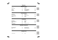
Contents BEFORE YOU DRIVE Controls Locks & Alarm Seats Seat Belts Airbag SRS Mirrors 3 4 10 12 15 18 Windows Sunroof Heating & Ventilation Interior Equipment In-Car Entertainment Load Carrying 20 21 23 25 28 29 DRIVING CONTROLS Instruments Warning Lights Starting & Driving Catalytic Converter Gearbox 30 32 34 37 39 Fuel System Wipers Lights & Indicators Switches Brakes 40 42 43 45 46 MAINTENANCE Maintenance Bonnet Opening Engine Compartment Engine Cooling System Brakes & Clutch 48 50 51 52 53 54 W
Introduction Welcome to your new Mini. This handbook, together with the other publications in the literature pack, provides all the information you need to gain maximum pleasure from owning and driving your new car. For your convenience, the handbook is divided into sections, each dealing with a particular aspect of driving or caring for the car. Take a little time to read each one and get to know your new Mini as soon as you possibly can.
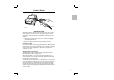
Controls 1 2 3 4 5 6 7 8 1. 2. 3. 4. 9 5. 6. 16 14 7. 8. 9. 10. 11. 12. 13. 14. 15. 16.
Locks & Alarm ALARM SYSTEM Your car is fitted with a sophisticated electronic anti-theft alarm and engine immobilisation system. In order to ensure maximum security and minimum inconvenience, you are strongly advised to gain a full understanding of the alarm system, by thoroughly reading this section of the handbook.
Locks & Alarm LOCKING THE CAR Before locking the car, ensure all doors, windows, sunroof, bonnet and luggage compartment apertures are securely closed. THE KEY MUST ALWAYS BE USED TO LOCK THE CAR. USING THE HANDSET TO ARM THE ANTI-THEFT ALARM, WILL NOT LOCK THE CAR. Operating Tip ..........
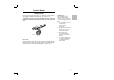
Locks & Alarm IMPORTANT H2118 Interior locking Both doors can be locked from inside the car by moving the latch rearwards (move the latch forwards to unlock). H2157 Luggage compartment lock Turn the appropriate key anti-clockwise to lock and clockwise to unlock. turn the handle anti-clockwise to open. 6 Using the key to operate the door and luggage compartment locks, will NOT arm or disarm the anti-theft alarm system.
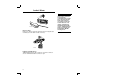
Locks & Alarm H2130 ARMING THE ALARM The handset has two buttons which, when pressed, send a coded radio signal to a receiver in the car. The ’padlock’ symbol button activates, and the plain button de-activates the following security features: • The perimetric alarm (protects the door, bonnet, and luggage compartment apertures). • Electronic engine immobilisation (described previously). If the alarm sounds To silence the alarm, press the plain handset button.
Locks & Alarm WARNING! Keep the Security Information card, key tag, spare handset and keys in a safe place - NOT in the car. H2155 KEY AND HANDSET NUMBERS You have been supplied with two handsets and two sets of keys, comprising: • A large plastic handled key for operating the starter switch. • A small all-metal key which operates the door and luggage compartment locks. • A larger all-metal key which operates the fuel filler cap lock.
Locks & Alarm WARNING! The handset contains delicate electronic circuits and must be protected from impact and water damage, high temperatures and humidity, direct sunlight and the effects of solvents, waxes and abrasive cleaners. H2121 HANDSET BATTERY The handset battery should last for approximately three years, dependent upon use. When the battery needs replacing, the operating range of the handset will reduce.
Seats WARNING! 3 DO NOT adjust the seats when the car is moving. DO NOT allow front seat occupants to travel with the seat backs reclined steeply rearwards. 2 H2127 1 Forward/backward adjustment Lift the lever (1) and slide the seat into position. Make sure the seat is locked in position before driving. Backrest adjustment Rotate the handwheel (2) to adjust. Head restraint adjustment Lift or push down on the restraint, until level with the back of the head.
Seats 1 2 H2159 Rear seat access levers Lift the lever (1) upwards to fold the backrest forwards. Pull the lever (2) to fold the whole seat forwards. For Your Safety ......... Make sure the backrest is secure before driving.
Seat Belts SEAT BELT SAFETY The seat belts supplied with your car are intended for use by adult sized occupants and must be used by one occupant only. Ensure that all passengers are securely strapped in at all times and be sure to observe the following precautions: • Adjust seat belts to eliminate any slack. Do not pull the belt away from the body - to be fully effective, the seat belt must remain in full contact with the body at all times.
Seat Belts For Your Safety ......... Where possible, rear seat passengers should adjust their position (moving nearer to or further away from the centre of the car) to enable the seat belt webbing to cross the shoulder without pressing on the neck. H2123 WARNING! Fastening the belt Pull the seat belt steadily across the body and, ensuring the webbing is not twisted, insert the metal tongue plate into the appropriate buckle - a ’click’ indicates that the belt is securely locked.
Seat Belts Caring for seat belts Regularly inspect the belt webbing for signs of fraying, cuts and wear, also pay particular attention to the condition of the fixing points and adjusters. Avoid contaminating the webbing with polish, oil and chemicals (see ’Cleaning & car care’). Three tests for checking seat belts 1. With the seat belt fastened, give the webbing near the buckle a quick upward pull - the buckle should remain securely locked. 2.
Airbag SRS The airbag supplementary restraint system (SRS) provides additional protection for the driver in the event of a SEVERE FRONTAL IMPACT ON THE VEHICLE. For Your Safety ......... Always remember; the airbag SRS provides ADDITIONAL protection in a frontal impact only; it does not replace the need to wear a seat belt. Inflation and deflation of the airbag take place very quickly and it will not protect against the effects of secondary impacts that may occur.
Airbag SRS For Your Safety ......... After inflation, some airbag components are hot - DO NOT touch until they have cooled. WARNING! H2148B How the airbag SRS works In a frontal collision, a sensor monitors the force of the impact to determine whether the airbag should be inflated. The airbag, contained within the steering wheel centre pad, will inflate in SEVERE frontal collisions only, It will NOT inflate in the event of side or rear impacts, roll over accidents, or minor frontal impacts.
Airbag SRS Service information After 10 years from the date of registration (or installation date of a replacement airbag SRS), some components will need to be replaced by a Rover dealer (see airbag module replacement date shown on page 2 of the Service Portfolio book), who should stamp and sign the appropriate page once the work is completed. In addition, ALWAYS contact your Rover dealer if; • the airbag inflates. • the front of the car is damaged (even if the airbag has not inflated).
Mirrors H2143 Exterior mirrors Adjust the exterior mirrors to give the required view from the driver’s seat position. H2111 Interior mirror Adjust the interior mirror to give the required view from the driver’s seat. The mirror can be dipped to reduce headlight glare from following vehicles; • Move the lever at the bottom of the mirror towards the windscreen. • Pull the lever back to restore normal visibility. 18 For Your Safety .........
Mirrors Operating Tip .......... Always return the sun visor to its stowed position when not in use - the sun, reflected in the vanity mirror, could scorch the seats. H2129 Vanity mirror To use the vanity mirror, pull down the passenger’s sun visor.
Windows For Your Safety ......... Ensure that children are kept clear while operating the windows. H2158 Front windows Turn the handle to open or close window as required. Rear ventilator windows (illustrated) To open, pull the catch forwards, then push outwards (as arrowed). To close, pull the centre of the catch inwards, then push rearwards until the catch is felt to ’snap’ into the locked position.
Sunroof Operating Tip .......... If you want to drive with the sunroof partially open: Open the sunroof fully and then close it to the desired position - this will keep wind noise to a minimum. Don’t operate the sunroof when it is obstructed, or covered in ice or snow - damage could be caused. Always close the roof when the car is left unattended. H2164 SUNROOF (if fitted) The sunroof can be operated when the starter switch is turned to position ’I’ or ’II’.
Sunroof H2160A Emergency operation If the electric motor will not close the sunroof, it can be closed manually by following the procedure below. 1. Remove the circular access plug situated in the roof lining to the rear of the sunroof. 2. Insert the cranked key into the drive spindle and turn it clockwise to close the roof. See your Rover dealer and have the fault rectified as soon as possible.
Heating & Ventilation H2117 The heating and ventilation system provides fresh or heated air to the interior of the car. Air outlets are provided to the windscreen, face and feet - the location of the vents is shown in the illustration above. The heater requires heat from the engine in order to supply heated air to the interior of the car. For this reason, full heating is not available unless the engine is running and has reached its normal operating temperature.
Heating & Ventilation Operating Tip .......... Maximum demisting/ defrosting Select the centre position on the air distribution control, pull the air temperature control fully out and set the blower switch to II’. H2170A 2 3 1 1. Air temperature control HEATED AIR: Pull the control out. UNHEATED AIR: Push the control in. 2. Air distribution control Left position: Foot level vents (with reduced air supply from windscreen vents). Centre position: Windscreen vents.
Interior Equipment 1 2 3 H2110 INTERIOR LIGHT Switch positions: 1. Light permanently on. 2. Light permanently off. 3. Light comes on automatically when a door is opened.
Interior Equipment Care Points ......... If the car battery is disconnected, the clock will need to be reset. CLOCK The clock face is illuminated automatically when the sidelights are switched on and the starter switch is turned to position ’I’ or ’II’. Adjusting the hands Press and turn the central adjuster to set the hour and minute hands.
Interior Equipment For Your Safety ......... DON’T drive with the glovebox open. An open glovebox could cause injury to a front seat passenger in the event of a collision. H2112 GLOVEBOX Press the upper edge of the glovebox lid to open. WARNING! Ashtrays are fire hazards DON’T use for waste paper or other combustible material. H2166 ASHTRAY Push the front of the ashtray on the right hand side to open.
In-Car Entertainment Care Points ......... ALWAYS unscrew and remove the aerial before entering an automatic car wash. H2137 RADIO AERIAL Your car is equipped with a detachable mast aerial mounted on the roof; unscrew to remove. Always check the available headroom and, if necessary, adjust the angle of the aerial before entering or leaving a garage or car park with insufficient headroom.
Load Carrying Rear window shelf Hard, heavy or pointed objects should not be carried on the rear window shelf - they may cause personal injury or damage the rear window itself during a sudden manoeuvre. Roof racks Make sure that you only fit a roof rack that is approved for your car. Your Rover dealer can provide details of all Rover approved roof racks.
Instruments Operating Tip .......... Driving on twisting or hilly roads may adversely affect the accuracy of the fuel gauge. It is advisable to check the fuel level when the car is travelling on a straight level road. 1 2 3 4 5 H2151 1. Speedometer Indicates road speed in miles per hour and/or kilometres per hour. 2. Total distance recorder (odometer) Indicates the total distance travelled by the car. 3.
Instruments 3 H2150 6 7 6. Voltmeter (if fitted) Indicates battery voltage. During normal driving, the pointer should register between 12 and 15 volts depending on road speed and electrical loads. If the pointer falls into the lower RED zone while driving, the battery is receiving insufficient charge. Switch off unnecessary electrical equipment, and if the pointer remains in the RED zone seek qualified assistance.
Warning Lights 4 H2153A 3 5 6 2 5 1 1. Low oil pressure - RED Illuminates as a bulb check when the starter switch is turned to position ’II’ and extinguishes when the engine is started. If the light remains on, or illuminates whilst driving, stop the car as soon as safety permits and switch off the engine immediately. Seek qualified assistance before driving. 2.
Warning Lights 5. Direction indicators - GREEN The left or right warning light flashes in time with the left or right direction indicator lights, whenever they are operated. If either warning light fails to illuminate, or flashes very rapidly, this means that one of the indicator lights is not operating. Operating Tip .......... When the hazard warning lights are operated, both direction indicator warning lights will flash together. 6.
Starting & Driving WARNING! Once the steering lock is engaged, it is impossible to steer the car. DO NOT remove the key, or turn the starter switch to position ’0’, while the car is in motion. H2149A STARTER SWITCH & STEERING LOCK The starter switch uses the following sequence of key positions to operate the steering lock, electrical circuits and starter motor. ’0’ - Steering locked With the key removed, the steering column will be locked and the lighting circuits operational.
Starting & Driving Starting the engine 1. Check that the handbrake is on and the gear lever is in neutral. 2. Switch off all unnecessary electrical equipment. 3. Turn the starter switch to position ’III’ and release the key as soon as the engine has started. Do not press the accelerator pedal while starting and do not operate the starter for more than 10 seconds at a time. Wait for at least 10 seconds before trying to start the engine again.
Starting & Driving RUNNING-IN The engine, gearbox, brakes and tyres need time to ’bed-in’ and adjust to the demands of everyday motoring. During the first 600 miles (1,000 km) it is essential that you drive with consideration for the running-in process and heed the following advice: • Do not allow the engine to exceed 3,000 rev/min in any gear. • Do not exceed 60 mph (95 km/h). • Do not operate at full throttle in any gear. • Do not allow the engine to labour in any gear. • Avoid heavy braking.
Catalytic Converter WARNING! Exhaust temperatures can be extremely high, do not park on ground where combustible materials such as dry grass or leaves could come in contact with the exhaust system - in dry weather a fire could result. H2133A The exhaust system on your car incorporates a catalytic converter which converts poisonous exhaust emissions into environmentally less harmful gases, thereby reducing pollution.
Catalytic Converter Driving • Do not overload or excessively ’rev’ the engine. • Do not switch off the engine when the car is in motion with a drive gear selected. • Consult your dealer if you think your car is burning too much oil, as this will progressively reduce catalyst efficiency. • If a misfire is suspected, or the car lacks power while driving, provided the engine has reached its normal operating temperature, it may be driven SLOWLY (at risk of catalyst damage) to a Rover dealer for assistance.
Gearbox Care Points ......... Do not rest your hand on the gear lever when driving pressure from your hand may cause premature wear to the gear selector mechanism. Do not rest your foot on the clutch pedal when driving excessive wear to the clutch will result. H2146 Do not hold the car stationary on a hill by slipping the clutch. This will wear out the clutch. Always use the handbrake. The gear positions are indicated on the gear lever knob. Synchromesh engagement is provided on all forward gears.
Fuel System For Your Safety ......... Petroleum gases are highly inflammable and, in confined spaces, are also extremely explosive. Always take care when refuelling: • • H2152 FUEL FILLING The fuel filler is located in the rear left hand wing. Insert the larger all-metal key in the lock, turn it anti-clockwise and allow any pressure inside the tank to escape, before removing the cap. Remember to lock the cap after refuelling.
Fuel System WARNING! ALWAYS check for fuel leaks before resetting the fuel cut-off switch. H2103 FUEL CUT-OFF SWITCH The fuel cut-off switch is a safety device which, in the event of a collision or sudden impact, automatically cuts off the fuel supply. The switch is located on the left hand side of the engine compartment, mounted on the bulkhead. After the switch has been activated, it must be reset by pressing the rubber top before the engine can be restarted.
Wipers Care Points ......... DO NOT operate the wipers on a dry screen. DO NOT operate the wipers with the bonnet raised. H2145 WIPER CONTROLS The wipers and washers will only operate when the starter switch is turned to position ’I’ or ’II’. Single wipe Pull the lever down and release. NOTE: With the lever held down, the wipers will operate at high speed until it is released. Intermittent wipe Turn switch to first position. Normal speed wipe Turn switch to second position.
Lights & Indicators H2147 Direction indicators The direction indicators will only operate with the starter switch turned to position ’II’. • For a right-hand turn, push the lever up. • For a left-hand turn, push the lever down. The appropriate warning light on the instrument panel will flash GREEN while the direction indicators are operating. The indicators will cancel automatically once a turn has been completed. Operating Tip ..........
Lights & Indicators For Your Safety ......... The loading definitions alongside assume that all loads will be within the limits of the maximum permissible axle and vehicle weights. H2136 Headlight levelling The height of the headlight beams is affected by the distribution of weight inside the vehicle. Always ensure your headlights are adjusted so that the point at which they meet the road surface ahead of the car, provides adequate illumination, without dazzling other road users.
Switches 1 2 3 4 5 Operating Tip .......... The front and rear fog lights extinguish automatically when the main lighting switch is turned off. However, they will illuminate again automatically when the lights are next switched on unless switched off manually. H2154A FASCIA SWITCHES 1. Rear fog guard light Press the bottom of the switch to operate; the indicator light in the switch illuminates when the rear fog guard light is on.
Brakes BRAKING SYSTEM The hydraulic braking system operates through dual circuits; if one circuit should fail, the other will continue to function. However, in the event of a brake failure where only one circuit is operational, the car should only be driven slowly to the nearest Rover dealer exercise EXTREME CAUTION and be aware that much greater pedal effort and longer stopping distances will be required if one circuit has failed. The braking system is servo assisted.
Brakes WARNING! DO NOT drive with the handbrake applied, this could damage the rear brakes and axles. H2109 HANDBRAKE The handbrake operates on the rear wheels only and should not require adjustment. To apply the handbrake, pull the lever up. Always apply the handbrake fully whenever you park the car. To release, pull the lever up slightly, depress the button (arrowed in illustration) and fully lower the lever. Operating Tip ..........
Maintenance ROUTINE SERVICING The safety, reliability and performance of your car will depend partly on how it is maintained. Maintenance is the owner’s responsibility; make sure that all routine services and warranty inspections are carried out by a Rover dealer at the recommended intervals shown in the Service Portfolio book. You will find this book in the literature pack.
Maintenance SAFETY IN THE GARAGE If you need to carry out maintenance, observe the following safety precautions at all times: • Keep your hands, tools and clothing away from drive belts and pulleys. • If the car has been driven, DO NOT TOUCH exhaust and cooling system components until the engine has cooled. • DO NOT TOUCH electrical leads or components while the engine is running, or with the starter switch turned on.
Bonnet Opening WARNING! 3 4 2 1 H2162 1. From inside the car, pull the bonnet release lever. 2. Push the safety catch lever away from the front of the bonnet and raise the bonnet. 3. Unclip the support stay. 4. Fit the support stay into the bracket as shown. Closing the bonnet Raise the bonnet slightly to release the support stay, then replace the stay in the clip. Lower the bonnet onto the catch, then use the palms of both hands to press the bonnet fully down to engage the catch.
Engine Compartment 4 6 5 WARNING! While working in the engine compartment, always observe the safety precautions listed under ’Safety in the garage’ on a previous page. 3 1. Engine oil filler 2. Engine oil dipstick 3. Fusebox (engine compartment) 4. Brake reservoir 5. Clutch reservoir 6. Fuel cut-off switch 7.
Engine WARNING! Driving with the oil level below the ’MIN’ mark will damage the engine. Oil specification: 10W/30 engine oil, meeting RES.22.OL.G4 or ACEA A2:96. Suitable for use in temperatures between -20° C to +30° C (if climatic temperature falls outside these limits, seek advice from your dealer). H2104 OIL LEVEL CHECK & TOP-UP Check the oil level when the car is on level ground with the engine switched off. If the engine is warm, wait for at least two minutes before checking the level. 1.
Cooling System Coolant specification: A 50% mix of water and Unipart Superplus 3 Anti-freeze and Summer Coolant, or any ethylene glycol based anti-freeze meeting BS 6580 or BS 5117. H2106 COOLANT CHECK & TOP-UP Check the coolant level weekly when the engine is cold and, if necessary, top-up with a mixture of anti-freeze and water, so that the coolant is level with the horizontal seam half-way up the reservoir.
Brakes & Clutch Fluid specification: • • H2102 CLUTCH FLUID CHECK & TOP-UP The fluid level may fall slightly during use. However, any appreciable drop in level within a short period may indicate a leak and should be reported to a Rover dealer immediately. Topping-up Add fluid until the level reaches the bottom of the filler neck. Use only new fluid from sealed containers (old or used fluid, or fluid from an uncapped container, will absorb moisture and adversely affect performance).
Brakes & Clutch Fluid specification: • • H2105 BRAKE FLUID CHECK & TOP-UP The fluid level may fall slightly during use, but should not drop below the ’MIN’ mark on the side of the reservoir. Any appreciable drop in level within a short period may indicate a leak and must be reported to a Rover dealer immediately. Topping-up 1. Wipe the cap clean to prevent dirt from entering the reservoir. 2. 0Hold the terminal block steady to protect the electrical connections, and unscrew the cap. 3.
Washers Reservoir capacity: 2.3 litre (4 pints) H2120 WASHER RESERVOIR The windscreen washer reservoir is in the luggage compartment. Check the level every week and top-up with a mixture of water and a good quality, proprietary screenwash. To ease refilling, the reservoir can be lifted clear of its mounting bracket to rest on the luggage compartment floor. To prevent freezing in temperatures down to -7° C, use a mixture of 5 parts water to one of screenwash. A stronger solution of 2.
Washers H2163 WASHER JETS To adjust a jet, use a needle as a lever to reposition the jet hole. Direct the spray towards the upper half of the windscreen. If a jet becomes blocked, use a thin wire as a probe to clear the obstruction.
Wipers Care Points ......... Grease, silicone and petrol based products impair the blade’s wiping capability. • • H2125 WIPER BLADE REPLACEMENT 1. Lift the wiper away from the windscreen 2. With the blade at right angles to the arm, press the locking tab (arrowed in LH illustration). 3. Keeping the locking tab pressed, slide the wiper blade down the arm until it is clear of the arm’s hooked end. The blade can then be removed. Fitting replacement blades is a reversal of this process.
Battery Care Points ......... Used batteries are potentially dangerous; dispose at authorised waste sites only. After battery disconnection, the handset may need to be re-synchronised (see ’Handset battery’). After battery disconnection, the radio display may show ’CODE’. Enter the radio security code to restore operation (see ’In-car Entertainment’ book). H2115 Battery removal & replacement The battery is located in the luggage compartment.
Battery Care Points ......... On older batteries, prevent corrosion of the battery lead clamps by liberally smearing the battery terminals with petroleum jelly (e.g. Vaseline). See ’Care Points’ and WARNING! on previous page. H2114 Battery maintenance The battery is a low-maintenance type, and during normal use in temperate climates, will not require topping-up. If it is necessary to top-up the electrolyte, proceed as follows: 1. Remove the battery from the car and stand it on a level surface. 2.
Battery Battery charging Before charging, the battery must be removed from the car and the electrolyte topped-up above the minimum level (see previous pages). Batteries generate explosive gases, contain corrosive acids and produce levels of electric current high enough to cause serious burns. Always observe the following precautions: • • • • • • Disconnect the battery charger from the power supply before attaching the charger leads to the battery.
Tyres Tyre care Always drive with consideration for the condition of the tyres, and frequently inspect the tread and side walls for punctures and signs of damage. The most common causes of tyre failure are: • Bumping against kerbs. • Driving over kerbs and deep pot holes. • Driving on unmetalled roads. • Driving with over or under-inflated tyres. Tyre pressures Incorrectly inflated tyres will wear rapidly, or unevenly, and may also seriously affect the car’s stability, road handling and fuel economy.
Tyres Punctured tyres Your car is fitted with tubeless tyres, which will not normally lose air immediately a sharp object penetrates the casing (provided the object remains in the tyre!). However, if you are aware that a tyre is punctured, drive at a reduced speed and with caution until the spare wheel can be fitted. Always have punctured tyres permanently repaired or replaced as soon as possible. Replacing tyres Wheel rims and tyres are matched to suit the handling characteristics of the car.
Cleaning & Car Care WARNING! Some high pressure cleaning systems will penetrate door, window and sunroof seals, and damage lock mechanisms. DO NOT aim water jets directly at components that might easily be damaged. H2122A WASHING YOUR CAR If the car is particularly dirty, use a hose to flush grime and grit from the surface prior to washing. Then wash the car using a clean, grit-free sponge and cold or lukewarm water containing a good quality wash and wax shampoo.
Cleaning & Car Care Protecting paint damage After washing, examine the paintwork for damage. Treat paint chips and scratches with a Rover paint touch-up pencil. If the damage has revealed bare metal, use a coloured primer first, then apply the base coat and finish off with a lacquer pencil, if appropriate. Carry out this treatment after washing but before polishing or waxing.
Cleaning & Car Care Wiper blades Wash in warm soapy water. DO NOT use spirit or petrol based cleaners. Fabric sun roof Wash with soapy water and a sponge, using a brush to remove stubborn dirt if necessary. If using a hose, avoid directing the water jet directly at the seal between sun roof and roof panel. NEVER use abrasive cleaners, or spirit, petroleum and chemical based cleaning agents. Occasionally open the roof and clean dirt and debris from the roof frame.
Cleaning & Car Care H2126A Body drainage points In muddy conditions, the door and body drainage points (shown in illustration) could become blocked. From time to time use a probe (preferably made from wood or plastic - not metal) to clear any build up of debris that might obstruct drainage.
Cleaning & Car Care CLEANING THE INTERIOR Plastic materials: Clean with diluted upholstery cleaner or warm water and a non-detergent soap (to achieve a matt, sheen-free, finish). Fabrics: Clean with upholstery cleaner. Leather: Seats and any other trim features should be cleaned with warm water and a non-detergent soap. Dry and polish the leather with a clean, dry, lint-free cloth. Carpet: Clean with diluted upholstery cleaner.
Emergency Towing H2209 Towing for recovery If your car is to be towed, most qualified recovery specialists will use wheel lift equipment to suspend the front wheels. However, if it is necessary for the car to be towed with all four wheels on the ground, use the front towing eye, located beneath the front bumper and follow this procedure. Before towing: 1.
Emergency Towing For Your Safety ......... DO NOT use the lashing points for towing another vehicle, trailer or caravan. • H2183A Transporter or trailer lashing If your car should require transporting on the back of a trailer or transporter, only use the front towing eye and the recommended lashing points on either side of the rear subframe, illustrated above - DO NOT secure lashing hooks or trailer fixings to other parts of the car.
Wheel Changing CHANGING A WHEEL Before changing a wheel, apply the handbrake and select 1st gear. If jacking on a slope, place chocks at the front and rear of the wheel diagonally opposite the one to be removed. The steel spare wheel and tool kit are stowed in the luggage compartment. For Your Safety ......... If possible, change the wheel away from the main thoroughfare. • • • Ensure passengers get out of the car and wait in a safe area away from other traffic.
Wheel Changing Changing the wheel IMPORTANT: If the wider 175/50 tyres are fitted to the car, refer to the important information below before changing the wheel. Before raising the car, slacken the wheel nuts half a turn. Then, using the wheel nut spanner to turn the jack screw, raise the car until the tyre is clear of the ground. Remove the wheel nuts and wheel (see ’Locking wheel nuts’).
Wheel Changing IMPORTANT 2 1 4 3 A code number is stamped on the face of the socket. Ensure the number is recorded on the Security Information Card supplied with the literature pack. Quote this number if replacements are required. For security reasons, DO NOT keep the card in the car. H2124A LOCKING WHEEL NUTS One locking wheel nut is fitted to each road wheel.
Fuses In brief .......... Fuses are simple circuit breakers, which protect the car’s electrical equipment by preventing the electrical circuits from being overloaded. A blown fuse may be indicated when the item of electrical equipment it protects stops working. C B A 1 2 3 4 5 6 7 8 9 For Your Safety ......... Turn off the starter switch and all electrical equipment before changing a fuse. Only replace a fuse with one of the same, or lower, rating. H2165A MAIN FUSE BOX - Checking or renewing a fuse 1.
Fuses MAIN FUSE BOX (inside the car) Fuse No Rating (amps) Circuits protected A1 A2 A3 A4 10 10 10 10 A5 A6 A7 A8 A9 15 - Headlight main beam - RH Headlight dipped beam - RH Side and tail lights - RH Alarm system, instruments, engine management Heater blower - B1 B2 B3 B4 B5 B6 B7 B8 B9 15 10 10 10 10 20 15 15 15 Driving lights Rear fog guard light Headlight levelling Ignition auxiliaries, radio Airbag SRS Alarm system and horn Sunroof Wipers Engine cooling fan C1 C2 C3 C4 10 10 10 10 C6 15 C
Fuses H2167 ENGINE COMPARTMENT FUSES Four fusible links are situated in a small fuse box at the front right hand side of the engine compartment. These protect the wiring between the battery and the main fuse box, and should be checked if an electrical failure appears to have affected a number of different systems, or one which has not caused a fuse to fail in the main fuse box.
Fuses H2168 A single 15 amp fuse, located on the right side of the engine compartment protects the front fog lights (if fitted).
Bulb Replacement 5 2 Care Points ......... Before replacing a bulb, turn off the lighting switch to avoid any possibility of a short circuit. Only replace bulbs with the same type and specification. 3 4 H2169 6 1 Headlight (and sidelight) 1. Remove the screw and headlight finisher. 2. Using a screwdriver as a lever (see illustration), lever the headlight to the left (looking towards the front of the car), and spring it free of the retaining screw (arrowed in illustration).
Bulb Replacement 3. 4. 5. 6. screws also control headlight alignment and, for this reason, must not be removed; they are mounted in a pliable material with sufficient flexibility to enable the headlight to be sprung free without disturbing the alignment. Detach the plug from the back of the headlight, and pull back the rubber boot. Sidelight: Pull the bulb holder from the back of the headlight. Push and twist the bulb to remove. Headlight: Unhook both ends of the retaining clip, then remove the bulb.
Bulb Replacement 2 3 4 H2138 1 Fog and driving lights (if fitted) 1. Remove the screw at the base of the light. This will release the lens and bulb assembly from the lamp body. 2. Detach both electrical connectors. 3. Unhook both sides of the retaining clip, and pivot the clip away from the rear of the light. 4. The bulb can now be removed. When replacing a bulb, note that shaped cut-outs in the metal base plate ensure the bulb’s correct alignment. 80 Care Points .........
Bulb Replacement 1 2 3 H2142 Rear light unit Remove three screws to release the lens. The lens is made in two parts, which slot together. When replacing the lens, the upper part must be placed in position first; the lower part then ’capturing’ the upper as the screws are tightened. Push and twist anti-clockwise to remove a bulb. 1. Direction indicator. 2. Brake/tail light (Note the ’stepped’ bayonet fitting; this ensures that the twin filament bulb is replaced correctly). 3. Reversing light.
Bulb Replacement H2140 Rear fog guard light Remove two screws securing the lens to the body. Remove the lens, then push and twist the bulb anti-clockwise to remove it from the holder. H2132 Number plate light Remove two screws securing the lens to the light housing. Ease the light unit from its recess and pull the bulb to remove.
Bulb Replacement H2134 Side repeater light 1. Push the light unit firmly to the right to withdraw it from the front wing. 2. Twist the bulb holder anti-clockwise to release it from the lens. 3. Pull to remove the bulb from its socket. H2113 Interior light From the end opposite the switch, use a small, flat-bladed, screw driver to prise the light unit from the roof lining. Push and twist the bulb anti-clockwise to remove it from the bulb holder.
Bulb Replacement REPLACEMENT BULBS Headlight (halogen): 60/55 watts Auxiliary (halogen): 55 watts Sidelight: 4 watts Direction indicator: 21 watts Side repeater: 5 watts Reversing light: 21 watts Stop/tail light: 21/5 watts Fog guard light: 21 watts Number plate light: 5 watts Interior light: 10 watts 84 GLB 472 GLB 453 GLB 233 GLB 382 GLB 501 GLB 382 GLB 380 GLB 382 GLB 239 GLB 245
Parts & Accessories SERVICE PARTS & ACCESSORIES Only Rover dealers are able to provide the full range of recommended parts and accessories that meet our rigorous standards of safety, durability and performance. It makes sense, therefore, to always consult a Rover dealer regarding the suitability, installation and use of any parts and accessories. Travelling abroad In some countries it may be illegal to fit parts that have not been made to the vehicle manufacturer’s specification.
Vehicle Identification 1 1 2 H2139 3 IDENTIFICATION NUMBERS 1. Vehicle identification number (VIN) Stamped on a metal plate attached to the right hand wing valance. Also, as a deterrent to car thieves and to help the police, the VIN is etched into the windscreen and rear window. The exterior body colour and interior trim codes are also stamped on the VIN plate and should be quoted if paint or trim items are required. 2. Body number Stamped on a plate attached to the bonnet locking platform. 3.
Technical Data Engine 3 Capacity ................................................................ 1275 cm Firing order ............................................................ 1-3-4-2 Idle speed .............................................................. 875 rev/min Fuel........................................................................ 95 RON UNLEADED to EN 228 specification Ignition system Type ......................................................................
Technical Data Weights Approx unladen weight (full fuel tank, excluding options) ................................................ 715 kg .............................. 1576 lb Maximum gross vehicle weight ............................ 1050 kg ............................ 2315 lb Maximum rear axle weight .................................... 510 kg .............................. 1124 lb Maximum roof rack load* .................................... 50 kg ................................
Technical Data FUEL CONSUMPTION The fuel consumption figures shown below have been calculated using a standard testing procedure (the new EC test procedure from Directive 93/116/EC), and produced in accordance with The Passenger Car Fuel Consumption (Amendment) Order 1996. Under normal use, a car’s actual fuel consumption figures may differ from those achieved through the test procedure, depending on driving technique, road and traffic conditions, environmental factors, vehicle load and condition.
Index A Accessories Aerial Airbag SRS Alarm system Anti-freeze Anti-theft alarm Anti-theft alarm indicator Ashtray 85 28 15, 32 4 53 4 32 27 B Battery Battery charging Body number Bonnet opening Brake fluid level Brake pads Braking system Bulb replacement 59 32 86 50 55 46 46, 54 78 C Capacities Car care Catalytic converter Child seats Cleaning Clock Clutch fluid level Controls Cooling system 88 64 37 13 64 26 54 3 53 D Data Demister (rear screen) Dimensions Dipstick - engine oil Direction indicators
Index P Parking Parts Poisonous fluids Polishing Pre-tensioners Punctured tyres T 35 85 49 65 14 63 Tachometer Technical data Temperature gauge Towing Towing for recovery Tyre pressures Tyres 28 28 28 45 45 29 29 36 V R Radio Radio aerial Radio/cassette player Rear fog guard light Rear screen demister Rear window shelf Roof rack Running-in S Safety in the garage Seat belt safety Seat belts Seats Security information card Service Portfolio book Side repeater light Sidelights Snow chains Spare wheel Spe