Ranger Auto - Drive Owners Manual Model No. 5377 – 12HP. WARNING • • • • A mower is a high speed cutting tool. Safety precautions must be observed to reduce the risk of accident. Careless or improper use may cause serious injury. Be sure that you read and fully understand the contents of this Owner’s Manual. Should any point be unclear, contact Rover-Scott Bonnar Limited, in your State or an authorised Rover-Scott Bonnar Service Agent for assistance.
SAFETY INSTRUCTIONS • A mower user must be in good physical condition and mental health and not under the influence of any drug or alcohol which might impair vision co-ordination or judgement. • Do not use a mower when tired or fatigued. Lack of alertness may cause serious injury. • Know your controls. Read and understand Owner’s Manual before operating mower. Learn how to stop the mower in an emergency. Refer Operator’s Instructions. • Do not lend or sell the mower without the Owner’s Manual.
SAFETY FEATURES Traction drive, blade drive and seat safety interlock Low centre of gravity, stable wide track Enclosed drives Parking brake Full footrests Convenient – easy to operate controls 1
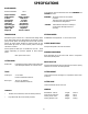
SPECIFICATIONS ROVER RANGER Machine Model No. Engine Model No. Single Cylinder 4 Stroke Fuel Capacity Oil Capacity Lubrication Spark Plug type Spark Plug gap Ignition type Engine Oil 5377 To emphasise special information the words WARNING and CAUTION are used. 281707 Briggs & Stratton 12Hp 465cc 4.0 Litres 1.42 Litres Gear Impellor Champion CJ8 0.7 to 0.8mm Magnetron 10w-30 or SAE 30 WARNING: The safety of the user and others involved. Personal injury may result should this information be disregarded.
LOOSE PARTS KIT USE QTY DESCRIPTION On steering shaft Secure steering wheel to shaft Fitted to cutter head On stone guard pivot rod In groove in pivot rod To start machine 1 1 1 1 1 1 1 Steering wheel Roll Pin Stone Guard Assy. Spring Stone Guard ‘E’ Clip Ignition Keys Plug Spanner SETTING UP INSTRUCTIONS Fig. 4 Fig. 2 INSTALL STEERING WHEEL 1. Slip steering wheel over steering shaft and align the wheel hole with the shaft hole; 5. 2.
BEFORE OPERATING FILL FUEL TANK – See Safety Instructions. FILL CRANKCASE WITH OIL The rider mower may be delivered without oil in the crankcase. Oil must be added before attempting to start the engine. 1. Place machine on level surface. Ensure that the oil plug is securely tightened. Clean around dipstick. 2. Unscrew and remove dipstick from oil filler tube. 3. Insert funnel into filler tube and slowly add oil in accordance with the engine manufacturer’s direction.
OPERATING INSTRUCTIONS AUTO – DRIVE OPERATION Forward and backward movement of the mower is controlled by the drive selector pedal. As with a motor vehicle, speed is controlled by the amount of pressure on the drive selector pedal. Ensure that the mower user is familiar with this means of operation before operating the mower, particularly in tight or confined areas. TO START ENGINE ENGAGING CLUTCHES 1. 2. 3. 4. 5.
MAINTENANCE INTERVAL CHART Change Oil (Initial) Change Oil (Periodic) Check Interlock Check Cutting Blades Check Cutting Unit Brake Check Rear Wheels Brake Lubricate Pivot Points Lubricate Drive Chain Lubricate Throttle Cable Grease Front Axle Spindles Service Air Cleaner Check Spark Plug Check Drive Belts Check Drive Chain Check Tyre Pressure Clean Outside of Engine Clean Cutter Housing Paint Chipped Surfaces See Page 6 6 11 9 9 7 7 7 7 6 6 10 10 4 - 5 Hours X 25 Hours 50 PERIODIC SERVICE EVERY 25 HRS
MAINTENANCE COOLING SYSTEM The Ranger has an air cooled 4 stroke engine. It must be cleaned frequently. Remove any build-up of grass, dirt or other debris from the 1. Cylinder; 2. Cylinder head cooling fins; 3. Cooling air intake screen and; 4. Carburetor governor levers and linkages. This will ensure adequate cooling and correct engine speed. THROTTLE CONTROL Proper choke and stop switch operation is dependant on adjustment of remote controls – 1. Loosen outer cable clamp screw (D) on engine; See Fig.9.
MAINTENANCE - - Cutter Drive Lever Pivot; Clutch/brake pedal pivot; See Fig.15 Tie rod ball ends; Fig.11 All connecting rod pivot points. WHEEL REMOVAL NOTE: All ball bearings are sealed and require no maintenance. CUTTING UNIT: Remove spark plug lead and disengage cutter drive before working on cutter unit, to prevent accidental starting of the engine. Before using machine always inspect cutting unit to see that the cutting disc, blades and blade fixings are not worn or damaged.
MAINTENANCE PARKING BRAKE CUTTER HEAD BRAKE Should always be checked for operation after clutch/brake rods have been adjusted. Should regularly be checked for operation. PAD REPLACEMENT 1. Remove ‘R’ clip and push rod pin (See Fig.19) 2. Remove brake pivot bolt (B) and two spacers (See Fig.19) 3. Remove brake plate assembly 4. Drill out pad retaining rivets 5. Rivet replacement pad in position 6. Refit in reverse order. CUTTER DRIVE ADJUSTMENT 1. 2. 3. Move Cutter Height Selector Lever to No.
MAINTENANCE AUTO DRIVE The Auto-Drive friction plates and drive pulleys are factory set for travel required along key shaft and this should not need adjusting. If during operation it is found that the relationship between forward and reverse has become unbalanced adjust as follows:1. Loosen locknut (A) Fig.22 2. Centralise engagement lever (D) with friction plates between drive pulleys, Fig.23 3. Re-tighen locknuts (A), Fig.22 Fig. 22 CONTINUOUS BELT This can be adjusted as follows:1.
MAINTENANCE STEERING RODS SAFETY INTERLOCK SYSTEM Should not normally require resetting. The safety interlock system has been designed for your protection and should not be tampered with. It gives the Ranger the following characteristics. 1. Loosen rod lock nut; (A) See Fig.11 2. Release the fixing bolt; 3. Turn tie rod end to adjust for length clockwise to shorten, anti-clockwise to lengthen 4. Replace the fixing bolt and tighten; 5. Tighten rod lock nut; 6. Make sure rod is free to pivot.
SAFETY AND INSTRUCTION DECALS Safety and Instruction decals are mounted on the RANGER Rear Engine Rider. Replace any that become damaged or illegible.
CIRCUIT DIAGRAM AND SPARES ITEM DESCRIPTION PART No. 1 2 3 4 5 6 7 8 9 10 11 12 13 14 KEY SWITCH KEY BLADE SWITCH BRAKE SWTICH SOLENOID BATTERY FUSE POWER LEAD EARTH LEAD EARTH STRAP WIRING LOOM SEAT SWITCH SEAT PANEL SW.
TROUBLE SHOOTING PROBLEM Engine loses power Engine over heats Mower vibrates abnormally Cutter does not rotate Mower does not drive Engine does not start, hard to start, loses power, or fails to keep running POSSIBLE CAUSES 1. Oil level in crankcase in low 2. Cooling fins and air passages under engine blower housing are blocked 3. Engine load is excessive 4. Air cleaner is dirty 5. Dirt or water is in fuel system 1. Add oil to crankcase 2. Remove obstruction from passages 3.
RANGER AUTO – DRIVE SPARE PARTS LIST ITEM PART No. DESCRIPTION * COMMON HARDWARE ITEM 1 2 3 4 5 6 7 8 9 10 11 12 13 14 15 16 A07937 A12005 A07999 A12001 A12002 A12009 A12010 A12011 * * * A03422 A03421 Fuel Tank Fuel Tank Cap Fuel Tank Bracket Fuel Tank Strap – Front Fuel Tank Strap – Rear Fuel Line – ¼ ID Hose Clamp Fuel Line Retainer ½” Copper Half Clip ¼” x ⅝” UNC Hex Bolt ¼” UNC Std.
16
RANGER AUTO – DRIVE SPARE PARTS LIST ITEM PART No.
18
RANGER AUTO – DRIVE SPARE PARTS LIST ITEM PART No.
20
RANGER AUTO – DRIVE SPARE PARTS LIST ITEM PART No. DESCRIPTION ITEM PART No.
22
RANGER AUTO – DRIVE SPARE PARTS LIST ITEM 1 2 3 4 5 6 7 8 9 10 11 12 13 14 15 16 17 18 19 20 21 22 23 24 25 26 27 28 29 30 31 32 33 34 35 36 37 38 39 40 41 42 43 44 45 46 47 48 49 50 51 52 53 54 55 56 57 58 59 60 61 62 63 PART No.
RANGER AUTO – DRIVE SPARE PARTS LIST ITEM PART No.
Warranty Conditions: Australia Only Rover-Scott Bonnar Limited warrant that this machine is free from defects in material and workmanship. This warranty is limited to making good or replacing any part which appears upon inspection by the manufacturer or his agent to be defective in material or workmanship. This warranty excludes fair wear and tear, or any damage caused by misuse or abuse.