
User guide

RN Commands Version 4.25, 11/1/2007 Page 25 of 25
809 University Avenue • Los Gatos, CA 95032 • 1-(408) 395-6539 • info@rovingnetworks.com
www.rovingnetworks.com
Important Notes:
Placing 3.3Vdc into the PIO’s while they are set as outputs will permanently damage the
radio modules. The failure mode is short across GND and VCC. Use a 10KO resistor in
series or a 10KO pull up resistor for input and output PIO’s respectively.
• Make sure to connect a common ground when using the external TX, RX inputs on the
0 – 3.3Vdc.
• For a 3 wire DB-9 interface (tx, rx, gnd only) connect/short CTS to RTS, Factory default
is hardware flow control enabled CTS and RTS connected.
• When using a 5.0Vdc Input, PIO’s require a 10K ohm series resistor. PIO’s are 0-3.3Vdc
not 5 volt tolerant.
• A null modem adapter is required to make a direct connection to a PC serial port.
Power Terminals for Evaluation Board
Inputs on P1 power connector can be 4.5VDC to 11.0VDC. There is internal regulation down
to 3.3VDC for all circuitry. Worst case power draw for the board is 80ma when the Bluetooth
radio/modem connection is established and transmitting. Power can be as low as 1ma to 25ma
average when the Bluetooth radio/modem is not connected depending on parameter settings.
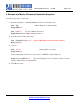
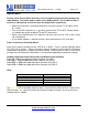
Hardware Communications Connections for Modules and Eval Board
Radio TX à RX of the application Micro Controller Unit (MCU)
Radio RX ß TX of the application Micro Controller Unit (MCU)
Radio RTS à CTS of the application Micro Controller Unit (MCU)
Radio CTS ß RTS of the application Micro Controller Unit (MCU)
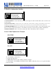
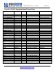
LEDs
.
MODE GREEN LED blink rate
Configuring 10 times per second
Startup/Config Timer 2 times per second
Discoverable/Inquiring/Idle Once per second
Connected Solid ON
The YELLOW LED should blink whenever data is transferred on either the RX or TX pins of the
DB9 serial port. It is a physical monitor of the actual voltage on the pins, and is not driven by
software from the module.