
User manual

BlueSentry User Manual
www.rovingnetworks.com
BlueSentry-um Version 1.0 3/12/2010
809 University Avenue • Los Gatos, CA 95032 • Tel (408) 395-6539 • info@RovingNetworks.com
~ 2 ~
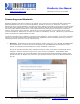
Overview
BlueSentry connects to industry standard sensors to provide wireless, remote signal monitoring and device
control in and commercial environments. It easily attaches to analog sensor outputs and automatically takes
continuous industrial measurements. Data is transferred wirelessly to PC and PDA clients using the Bluetooth
Serial Port Profile (SPP). The BlueSentry can also be paired with the Roving Networks BluePort XP serial adapter
or Fireplug USB dongle to create a wireless serial port connection. Software applications can control and acquire
data as if they were connected to a local serial port.
BlueSentry contains a built in ADC and smart Bluetooth radio. The device is programmed over Bluetooth via
simple ASCII commands. Both ASCII and binary data formats are supported. Upto 8 channels can be selected
as single ended or differential measurements.
Features
• Small form factor: 1.6” X 3.0” X 0.9”
• Eight 16 bit input A/D channels, input voltage 0-5VDC at upto 3000Hz sampling rate
• High power Class 1 Bluetooth radio (12dBm output transmitter, 100 meter range) with integral chip
antenna
• Equipped with Serial Port Profile, BlueSentry can be configured as either Master or Slave
• Two on board FET switches for powering external sensors
• Two general purpose inputs/outputs (15ma drive) for control
• Low power 6-12VDC (75ma) can run from 4 AAA batteries
• Low power sleep and wake on connect options
• Screw post (power in, 2 ch), RJ45 (power in, 6 ch) and 12 pin internal header connections.
• External SMA jack Antennae option, order RN-800S-E.
Applications
The BlueSentry can be used for a host of sensor applications. Some of the possible applications are:
• Remote Temperature Sensor
• Wireless Motor Control
• Remote Motion Sensors
• Wireless control and monitoring
***WARNING**
BlueSentry channel inputs do NOT have input protection, care must be taken not to exceed the maximum input
voltage of +5VDC on any input, and the inputs should never be driven to negative voltages below GROUND. This
will cause permanent damage to the AD circuits.
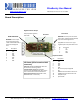
LEDs
When power is applied, both the YELLOW and GREEN LEDs will alternate about 10 times as the unit is self-testing,
then the GREEN LED will blink about once per second. Once a connection is made, the GREEN LED will blink 4
times/second, and the YELLOW LED blinks when DATA is sent or commands are received from Bluetooth. As the
data rate increases, this LED will flash more quickly. If the YELLOW LED comes on solid, and the GREEN LED
blinks a continuous pattern, the unit either cannot communicate to the Bluetooth radio, or has failed an internal
self-test. Power cycling may solve the problem.