RN-BT-SRL-UM Bluetooth Serial Adapter © 2011 Roving Networks. All rights reserved. RN-BT-SRL-UM-1.0 Version 1.
RN -BT -SR L-U M- 1.0 OVERVIEW Roving Networks offers a variety of Bluetooth serial adapters with different form factors and powering options (see Table 1). These adapters enable wireless connection to any legacy serial port and support bi-directional RS-232 or RS-422 signaling at a rate of up to 464 Kbps. To create a wireless cable replacement solution, simply attach the adapter to your device's RS-232 or EIA-232/422 port and connect to it over Bluetooth.
RN -BT -SR L-U M- 1.0 Turning the Adapter On & Off To turn the adapter on, press the red button for 1 second until the green and blue LEDS begin flashing and then release it. After a moment, the blue LED goes off and the green LED remain flashing to indicate the device is turned on and not connected. To turn the adapter off, press the red button for 1 second until the green and blue LEDs begin flashing and then release it. All the LEDs turn off.
RN -BT -SR L-U M- 1.0 Reducing Power when Disconnected Low-power connection mode disables the Bluetooth radio and LED timers when the adapter is disconnected. In low-power mode, the adapter cycles between active (discoverable and connectable) and low power deep sleep. This mode saves considerable power when the module is waiting for long periods of time without a connection. The trade off is additional latency when connecting or pairing.
RN -BT -SR L-U M- 1.0 CONFIGURATION SWITCHES The adapters have small configuration switches on the top. You need a paper clip or small screwdriver to flip them. Holding the adapter with the DB9 connector facing to the right, refer to Figure 1 for the switch numbering and on/off positions. Figure 1. Switches RN-240, RN-422 & RN-220-XP On RN-270 & RN-274 Off On 4 3 2 1 Off 4 3 2 1 Table 3 describes the functions controlled by the switches. Table 3.
RN -BT -SR L-U M- 1.0 CONFIGURATION The Bluetooth adapter operates in two modes: data mode (default) and command mode. While in data mode, the module is essentially a data pipe. When the module receives data, it strips the Bluetooth headers and trailers and passes the user data to the UART. When data is written to the UART, the module constructs the Bluetooth packet and sends it out over the Bluetooth connection.
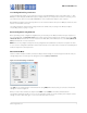
RN -BT -SR L-U M- 1.0 Local Configuration Using a Serial Port Connect the Bluetooth adapter to your computer’s serial port. (The RN-240M may require a null-modem cable, i.e., with DB9 pins 2 and 3 swapped; the RN-240F requires a straight cable). If your computer does not have a serial port, you can use a USB-to-serial cable such as the RN-USB-SERIAL to connect the Bluetooth adapter to your computer.
RN -BT -SR L-U M- 1.0 Figure 4. Enter Command Mode COMMAND SUMMARY All configuration information is stored in flash memory. The set command modifies the flash memory; however, the Bluetooth module only reads the configuration from flash memory when powering up or after a reboot. Table 4 shows some common configuration commands. Table 4. Common Configuration Commands Command Description SU,9600 Sets the UART baud rate to 9600. SN,myname Sets the Bluetooth name to myname.
RN -BT -SR L-U M- 1.0 MAKING A BLUETOOTH CONNECTION By default, the Bluetooth adapter acts as a slave and the PC is the master. You connect to the Bluetooth adapter using your computer’s Bluetooth device manager, which varies depending on the operating system. Regardless of the operating system, the process is the same: discovery, pairing, and connecting. Discovery When you turn on the Bluetooth adapter, the green LED should blink and the adapter should be discoverable.
RN -BT -SR L-U M- 1.0 Figure 6. Pair with the Bluetooth Adapter NOTE: You only need to pair with the adapter once. Connecting To establish a Bluetooth connection, open the adapter’s COM port from your application or a terminal emulator. When the COM port is open, the adapter’s green LED changes from blinking to solid on. The device remains connected until you close the COM port or turn off the Bluetooth adapter. Security Modes The Bluetooth adapter supports authentication.
RN -BT -SR L-U M- 1.0 SERIAL CONNECTOR SPECIFICATION The Bluetooth serial adapters have male or female DB9 connectors. Refer to Figure 7 and Table 5 for the pin-out. Figure 7. DB9 Connector Pins 1 5 6 9 Table 5.
RN -BT -SR L-U M- 1.0 APPENDIX A - NULL MODEM & FLOW CONTROL JUMPERS You can configure the adapter’s serial interface to enable flow control and null modem signaling. You access the jumper block by removing the cover from the Bluetooth serial adapter. Figures 10 and 11 show the jumper settings. WARNING: Flow control signals are NOT RS-232 signaling tolerant. If you enable these signals with the jumpers, do not exceed 3.3-V DC or permanent damage can occur. Figure 8.
RN -BT -SR L-U M- 1.0 Figure 9. RN-220XP Jumpers Male DB9 (Default Configuration) DTE 3 Wire Jumper 1 < > 2, 7 < > 8, 9 < > 10 1 3 5 7 9 2 4 6 8 10 Male DB9 DCE - Flow Control Enabled Jumper 3 < > 4, 5 < > 6, 7 < > 8, 9 < > 10 1 3 5 7 9 2 4 6 8 10 Male DB9 DCE - Flow Control Disabled Jumper 1 < > 2, 7 < > 9, 8 < > 10 1 3 5 7 9 2 4 6 8 10 www.rovingnetworks.
RN -BT -SR L-U M- 1.0 APPENDIX B - INSTANT CABLE REPLACEMENT You can use the Roving Networks adapters (with or without the FirePlug USB dongle, RN-USB-X) for cable replacement with the following steps: 1. Turn off the adapters and set the switches as shown in Figure 10. Figure 10. Cable Replacement Switch Settings Master Mode Auto Discovery & Auto Master Turned On On Slave Mode Auto Discovery Turned On Off On 4 3 2 1 Off 4 3 2 1 2. Power up both devices.
RN -BT -SR L-U M- 1.0 NOTES www.rovingnetworks.
RN -BT -SR L-U M- 1.0 Copyright © 2011 Roving Networks. All rights reserved. Roving Networks is a registered trademark of Roving Networks. Apple Inc., iPhone, iPad, iTunes, Made for iPhone are registered trademarks of Apple Computer. Roving Networks reserves the right to make corrections, modifications, and other changes to its products, documentation and services at any time.