RN-WIFLY-EVAL-UM WiFly Evaluation Kit © 2012 Roving Networks. All rights reserved. RN-WIFLY-EVAL-UM Version 1.
RN -W IFLY -E VAL-U M OVERVIEW This document describes the hardware and software setup for Roving Networks evaluation kits, which contain the hardware you need to evaluate the RN-171 or RN-131 WiFly 802.11 b/g modules. The RN-171 and RN-131 WiFly modules are mounted to evaluation boards. Each board contains status LEDs, connections for the programmer and UART interfaces, a voltage regulator, and easy access to GPIO pins.
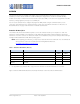
RN -W IFLY -E VAL-U M Figure 1. RN-131-EK Evaluation Board USB Connector LED Indicators UART Interface (J3) AP/WPS/Factory Reset Pushbutton (GPIO9) Reset Pushbutton Sensor Interface (J1) UART Interface (J3) 1 2 3 4 5 6 7 8 9 10 11 12 13 Sensors (J1) RX - input to evaluation board TX - output from evaluation board Pin Description 1 3.
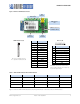
RN -W IFLY -E VAL-U M Figure 2. RN-171-EK Evaluation Board LED Indicators UART Interface (J4) PCB Trace Antenna AP/WPS/Factory Reset Pushbutton (GPIO9) Sensor Interface (J5) Sensor Interface (J5) 9 8 7 6 5 4 3 2 1 Pin Description 1 Sensor Power 2 Sensor 4 (3.3-V tolerant) 3 Sensor 5 (3.3-V tolerant) 4 Sensor 7 (1.2 V only) 5 Sensor 5 (1.2 V only) 6 Sensor 4 (1.
RN -W IFLY -E VAL-U M Table 3.
RN -W IFLY -E VAL-U M CONFIGURATION The WiFly module operates in two modes: data mode (default) and command mode. While in data mode, the WiFly module is essentially a data pipe. When the module receives data over Wi-Fi, it strips the TCP/IP headers and trailers and passes the user data to the UART. When data is written to the UART, the module constructs the TCP/IP packet and sends it out over Wi-Fi.
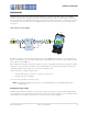
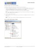
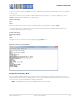
RN -W IFLY -E VAL-U M Configure the Module Using a Terminal Emulator To communicate with the module using a terminal emulator, perform the following steps: 1. Determine the COM port that was assigned to the USB cable. If you do not know the COM port number, you can find it using the Windows Device Manager, which is in the system tools. In the Device Manager, browse and expand the selection for Ports (COM & LPT). In the example shown in Figure 5, the port is COM9.
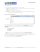
RN -W IFLY -E VAL-U M Enter Command Mode To enter command mode, perform the following steps in the terminal emulator: 1. Type $$$. You must type $$$ together quickly with no additional characters before or after them. The module replies with CMD to indicate it is in command mode. 2. Type show net to display the current network settings. NOTE: When a command completes, the terminal displays a prompt in the format where X.XX indicates the module’s firmware version.
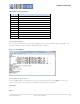
RN -W IFLY -E VAL-U M Table 4. Basic set & get Parameters Parameter Function adhoc Controls the ad hoc parameters. broadcast Controls the broadcast hello/heartbeat UDP message. comm Communication and data transfer, matching characters. dns DNS host and domain. ftp FTP host address and login information. ip IP settings. option Optional and infrequently used parameters. sys System settings, such as sleep and wake timers. time Realtime clock settings.
RN -W IFLY -E VAL-U M To disconnect from a network, type leave . The red LED blinks quickly when the WiFly module is not associated with an access point. If you want the module to associate with a network automatically upon booting (i.e., persistent configuration), use the set wlan command with the SSID name. For example, type: set wlan ssid roving1 save reboot When the module wakes or power cycles, the module attempts to associate with the network roving1.
RN -W IFLY -E VAL-U M Enable Ad Hoc Mode via Hardware To enable ad hoc mode using hardware, set GPIO9 high (3.3 V) at power up. For the RN-134 board, GPIO9 is on pin 1 on the jumper block (J2). For the RN-174 board, GPIO9 is on the J6 connector. Upon power up with GPIO9 high, the WiFly module creates an ad hoc network with the following settings: SSID: WiFly-GSX-XX, where XX is the final two bytes of the device’s MAC address IP address: 169.254.1.
RN -W IFLY -E VAL-U M Associate with an Ad Hoc Network The WiFly module can associate with an ad hoc network created by another device. Type the commands: set wlan ssid my_adhoc_network save reboot To associate with an ad hoc network without saving the changes to the module’s flash memory, use the join command, e.g., join my_adhoc_network . If DHCP is enabled, the WiFly device obtains an IP address automatically when it associates with the ad hoc network.
RN -W IFLY -E VAL-U M RESOURCES & RELATED DOCUMENTS For more information, refer to the following sources, which are available on the Support page on the Roving Networks website at http://www.rovingnetworks.com/support.
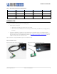
RN -W IFLY -E VAL-U M APPENDIX A: LEGACY EVALUATION KITS This appendix provides specifications for legacy Roving Networks evaluation kits. Table 6 provides an overview of the kits. Table 6. Evaluation Kit Hardware Hardware Description RN-131G-EVAL RN-134-K RN-174-K For RN-131 module For RN-131 module For RN-171 module Evaluation board Contains the WiFly module and connectors. USB-to-serial cable Links your computer to the evaluation board. Contains the Prolific chipset.
RN -W IFLY -E VAL-U M Figure 10.
RN -W IFLY -E VAL-U M Table 7.
RN -W IFLY -E VAL-U M Figure 11.
RN -W IFLY -E VAL-U M Figure 11. RN-174 Evaluation Board (Part 2 of 2) ISP Connector (J5) 2 4 6 8 10 12 14 16 1 3 5 7 9 11 13 15 Pin Description 1 GND 2 3.3 VDD 3 DMA UART TX 4 UART RX 5 FORCE AWAKE 6 RESET 7 DMA UART RX 8 UART TX 9 3.3 VDD 10 GND 11 GPIO9 12 GPIO4 13 GPIO5 14 GPIO6 15 GPIO8 16 Not Used Note: 2.
RN -W IFLY -E VAL-U M RN-134 & RN-174 Hardware Setup To set up the RN-134 and RN-174 evaluation kit hardware, perform the following steps: 1. Provide power to the board by soldering the provided 9-battery clip wire to the board (J7) and attaching a 9-V battery to the clip. 2. Connect the 10-pin serial cable to the evaluation board (J3). When looking at the top of the board, the cable should extend away from the board.
RN -W IFLY -E VAL-U M Table 9 shows the evaluation kit contents and ordering information. Table 9. Legacy Evaluation Kit Contents Kit Photo Contents RN-131G-EVAL Kit • • • • • • • RN-134: Evaluation board for RN-131 module RN-USB-SERIAL: USB-to-serial cable with male DB-9 connector RN-UFL-SMA-6: U.
RN -W IFLY -E VAL-U M NOTES: www.rovingnetworks.com Version 1.
RN -W IFLY -E VAL-U M Copyright © 2012 Roving Networks. All rights reserved. Roving Networks is a registered trademark of Roving Networks. Apple Inc., iPhone, iPad, iTunes, Made for iPhone are registered trademarks of Apple Computer. Roving Networks reserves the right to make corrections, modifications, and other changes to its products, documentation and services at any time.