
User`s guide

RN-WIFLYCR-UG
www.rovingnetworks.com Version 1.2r 4/30/13 page 60
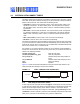
The first (or possibly multiple) byte sent to the module will likely be lost; therefore, you
should take care to send a preamble byte to wake the module before sending valid data
bytes. Alternatively, use the CTS input to wake the module and wait until it is ready to
accept data. To enable this setting, use the set sys trig 2 command.
3.6.1 UART Receiver & RTS/CTS Hardware Flow Control
The UART receive buffer is approximately 1,500 bytes. At lower baud rates (less than
115 K), the system can send data over TCP/IP without flow control.
Depending on the frequency and quantity of the data being sent, the comm parameters
optimize Wi-Fi performance by specifying when the system sends IP packets. To min-
imize latency and TCP/IP overhead, use the flush size or match character to send data
in a single IP packet. In most cases, you should set the flush timer to a large number
to avoid fragmentation. For high throughput, increase the UART baud rate, set the flush
size to 1,460, and set the flush timer to a large value so that full IP packets are sent.
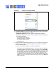
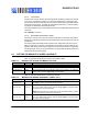
You can control packet forwarding in the following ways:
• set comm match <value> sets the value of the packet terminator. Each time the
module sees the match character it sends an IP packet. For example, set comm
match 0xd forwards a packet when the module sees a 0xd hex character.
• set comm size <value> sets the flush size, where <value> is the number of bytes
received before forwarding. The maximum is 1,460 bytes, which is the size of a
single Ethernet frame.
• set comm time <value> sets the flush timer, which is used to flush any partial
data sitting the RX buffer if no additional data is received for <value> ms. For
example the set comm time 1000 command causes the module to wait for 1 sec-
ond after no data was sent.
If the module will be sending more than a few hundred thousand bytes in a single trans-
action, you should enable hardware flow control. Your hardware must actively monitor
the CTS pin. Flow control is not enabled by default; you set it with the set uart flow 1
command.
It is possible to operate higher baud rates (i.e., greater than 115 K) without flow control
if the packets are uniform and you use an application protocol to ensure that the packet
data is delivered on the remote side before the next packet is sent. However, given
the uncertainty of packet delays in a TCP/IP network and the affects of interference and
retries inherent in wireless networks, flow control is typically required whenever large,
contiguous quantities of data are being written to the UART to guarantee no data is lost.
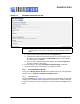
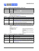
3.6.2 Setting GPIO Direction, Alternate Functions & Disabling LEDs
You control the GPIO pin direction and function using two commands:
• set sys mask
• set sys iofunc
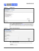
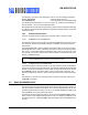
Note: On the RN-134 evaluation board revision 2, the resistor pack connecting
the RX and CTS signals is not correctly connected to the sensors. To wake
on UART RX, place a jumper from pin 3 on the evaluation board header to
pin 2 on the sensor header. To wake on UART CTS, place a jumper from
pin 10 on the evaluation board header to pin 3 on the sensor header.