Assembly Instructions ITM. / ART. # TM21RT56FPT1 IMPORTANT, RETAIN FOR FUTURE REFERENCE: READ CAREFULLY THE ITEM IS INTENDED FOR OUTDOOR DOMESTIC USE ONLY, NOT FOR COMMERCIAL USE. Fire Table Questions, problems, or missing parts? Before returning to the store please visit sunvilla.com, or contact our Customer Service Department at cs@sunvillahome.
CONTENTS • Warnings ................................................................ 1-4 • Diagram ................................................................... 5 • Assembly ................................................................ 6-7 • Operation ................................................................8-9 • Maintenance & Storage ................................... ...... 10 • Trouble Shooting ....................................................
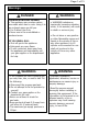
Page 1 of 13 Warnings DANGER CARBON MONOXIDE HAZARD ● This appliance can produce carbon monoxide which has no odor. Using it in an enclosed space can kill you. ● For Outdoor Use Only. ● Never use in the unventilated or enclosed areas. IF YOU SMELL GAS: ● Shut off gas to the appliance. ● Extinguish any open flame. ● If odor continues, keep away from the appliance and immediately call your gas supplier or fire department for help.
Page 2 of 13 Warnings WARNING ● The installation of this unit must adhere to local codes or either the National Fuel Gas Code, ANSI Z223. 1/NFPA54, OR CAN/CGA- B149.1, National Gas and Propane Installation Code. ● This unit is to be used with propane gas only! (sold separately), is not intended for natural gas. ● Do not use any solid fuel or charcoal for this unit. ● Do not use any more than 1/4in depth lava rocks/ pumice stones/ Lava Glass above the burner holes. Doing so will suffocate the flame.
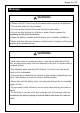
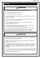
Page 3 of 13 Warnings WARNING ● Remove the PVC Cover from the firebowl before opening the appliance. ● Do not pour water into the firebowl. ● Do not use this firebowl if any part has been under water. ● Do not use this firebowl on vehicles or boats. Always operate the appliance on flat ground outdoors. ● Clean the battery contacts and the device prior to battery installation. ● Never lean over the open firebowl or place hands or fingers on the upper portion of an operational unit.
Page 4 of 13 Warnings WARNING ● Do not operate unit until all parts are fully assembled. ● Do not attempt to move it while in use. ● Do not use this firebowl for cooking. ● Young children should be carefully supervised when they are in the area of the appliance. ● Do not hang clothing or any other flammable materials from the fire pit, or place on or near the fire pit. ● Do not set the protective cover over the unit until it is turned off and completely cooled down.
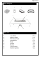
Page 5 of 13 Parts Diagram 1 3 2 4 7 6 5 8 9 Parts List 1 2 3 4 5 6 7 8 9 Lava Rocks Battery (AAA) PVC Cover Tank Seat Burner Body Screen Burner Control Knob Electric Ignition 2 box 1 pc 1 pc 1 pc 1 pc 1 pc 1 pc 1 pc 1 pc
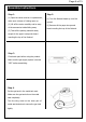
Page 6 of 13 Assembly Instructions Step 1: Step 2: (1) Open the carton and turn it upside down, (1) Turn the firebowl heads up on a flat make sure 4 pieces of it being open up. ground. (2) Lift off the carton carefully and be wary (2) Remove all the paper honeycomb of the accessories inside falling away. board rounding the top of the firebowl. (3) Take all the packing materials away except for the paper honeycomb board rounding the top of the firebowl.
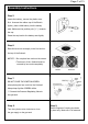
Page 7 of 13 Assembly Instructions Step 5: Locate the battery, remove the plastic cover first. Unscrew the rubber cap of the Electric Ignitor, place a AAA battery into the battery case. Make sure the positive pole ("+") towards - + the cap. Screw the cap back to the battery case tightly. Step 6: Place the lava rock averagely in the fire bowl on the top of the firebowl. NOTICE: * Do not place lava rocks on the screen. * The burner of the firebowl must be covered by lava rocks completely.
Page 8 of 13 Operation FOR YOUR SAFETY, READ BEFORE LIGHTING • Before performing a leak test, make sure that no sparks can occur and you are in a spacious outdoor area. • Connect the propane gas tank to the regulator and turn the valve on the unit to the “off” position. • Brush a soap and water mixture on all connections. • Make sure the igniter battery has been installed properly. The igniter will not operate otherwise.
Page 9 of 13 Operation LIGHTING INSTRUCTIONS 1. Turn the cylinder valve on the gas tank counter-clockwise to open the gas supply. 2. Close the storing door on the firebowl for the gas tank. 3. Press and hold the Electric Ignitor. Meanwhile, push and turn the Control Knob counter-clockwise to the "LOW" position. Keep pushing the Control Knob to light the burner . 4. After ignition, release the Electric Ignitor. Continue to push and hold the Control Knob for 45 seconds. 5.
Page 10 of 13 Maintenance & Storage To enjoy years of outstanding performance from your heater, make sure you perform the following maintenance activities on a regular basis: • Before performing any maintenance always disconnect propane gas tank. • Use warm soapy water for cleaning. Never use flammable or corrosive cleaning agents. • Keep the heating item free and clear from combustible materials. • Visually inspect burner for obstructions and keep tank enclosure free and clear from debris.
Page 11 of 13 Trouble Shooting PROBLEM Burner will not light using igniter Burner will not light with match The fire table emits a lot of black smoke when in use Sudden drop in gas flow, or a reduced flame height CAUSE Electrode and burners are wet SOLUTION Wipe dry with cloth. Igniter battery is dead or backwards Check that the AAA battery is inserted correctly in the igniter or replace the battery.Make sure the plastic wrap on the battery has been removed.
Page 12 of 13 Trouble Shooting Problem: Burner JUST LIGHT UP FOR SECOND AND WILL AUTOMATICALLY TURN OFF PILOT GUARD 1 2. 3 . THERMOCOUPLE IGNITION PIN 4 . IGNITION PIN THERMOCOUPLE 1. The thermocouple will be under the Pilot Guard on the top of the unit. Please remove the Pilot guard by unscrewing it from the metal bowl with a screw driver. 2. Once the Pilot Guard has been removed, you will have two components exposed; the copper one is your thermocouple.
Page 13 of 13 Warranty Information This product has been manufactured under the highest standards of quality and workmanship. We warrant to the original consumer that all aspects of this product will be free of defects in material and workmanship for one year from the date of purchase. A replacement for any defective part will be supplied free of charge for installation by the consumer. Defects or damage caused by the use of other than genuine parts are not covered under this warranty.