
Specifications

September 2012 Page
22
INSTALLATION: GENERIC SYSTEMS
The system Diagrams provided are only suggested schematics for generic systems and do not
purport to show all required components necessary to meet all required codes. Complex
systems should be designed by a professional heating system.
SYSTEM PLUMBING
CAUTION
GENERAL COMMENTS
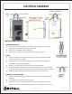
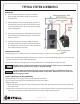
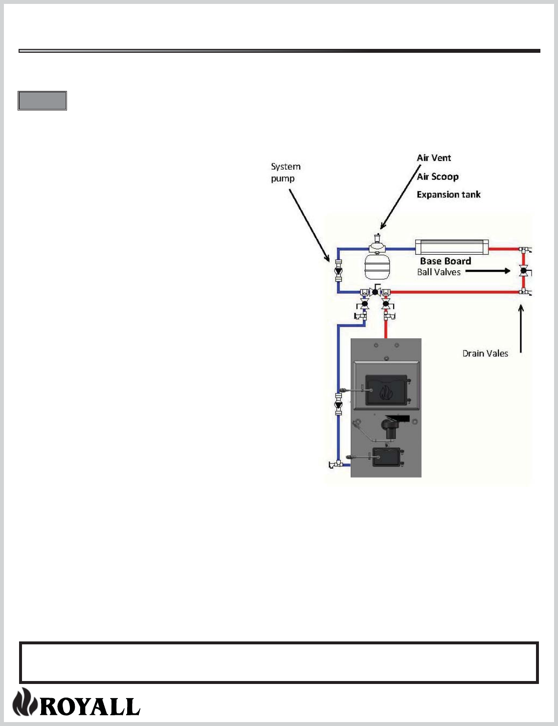
PIPING AT THE APPLIANCE
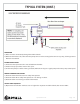
Base Board
The piping at the appliance does not change with most
applications In the applications drawings on following
pages it is not shown but is assumed to be as shown on
this page.
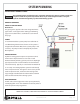
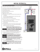
PUMPS
Is recommended that a system pump be installed to en-
sure ow through the boiler at all times. If the system is
designed for continuous ow, then a system pump is not
necessary. All pumps must be sized properly based on
ow requiems.
EXPANSION TANK
Hydronic heating systems require an expansion tank to
allow water to expand/contract as it heats or cools
without adversely a ecting system pressure. A diaphragm
type expansion tank is recommended. The tank must be
installed vertically. Typically it is attached to the bottom of
an air scoop. An existing hydronic system should already
have an expansion tank. Though it is not necessary to add
another expansion tank, ensure that the existing tank is
large enough to handle both the volume of the solid fuel
boiler and the volume of the existing system.
AIR ELIMINATION
Air will collect at the high points in the system, potentially
interrupting ow. An air vent should be located at points to
allow the system to be purged of air.
COMPLEX SYSTEMS SHOULD BE DESIGNED BY A HEATING PROFESSIONAL