
Datasheet


˖ˢˡ˙˜˗˘ˡ˧˜˔˟ʳ˗ˢ˖˨ˠ˘ˡ˧
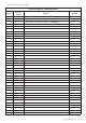
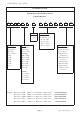
7. Performance specification :
*Insulation
1,000 MӨ or more
Apply 500V DC between protective coating
resistance and termination for 1 min, then measure
(Sub-clause 4.6)
*Dielectric No evidence of flashover Apply 100V(0402) 300V(0603) & 500V (0805,1206,1210,2010,
withstanding mechanical damage, arcing or 2512) AC between protective coating
voltage insulation break down and termination for 1 minute (Sub-clause 4.7)
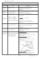
Natural resistance change per temp.
degree centigrade.
1ȍ~10ȍ : ± 400 PPM/͠ R
2-R1
Temperature 10.1ȍ~100ȍ : ± 200 PPM/͠
x 10
6
(PPM/к)
coefficient >100ȍ : ± 100 PPM/͠ R
1(t2-t1)
(0201 : >100ȍ ± 200 PPM/͠)R
1: Resistance value at room temperature (t1)
R
2: Resistance value at room temp. plus 100 к (t2)
(Sub-clause 4.8)
Short time Resistance change rate is Permanent resistance change after the
overload
± (1.0% + 0.1Ө) Max.
application of a potential of 2.5 times RCWV
for 5 seconds
(Sub-clause 4.13)
Test temperature of solder : 245
rк
*Solderability 95 % coverage Min. Dipping them solder : 2-3 seconds
(Sub-clause 4.17)
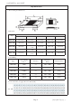
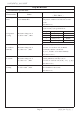
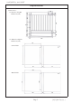
Wave soldering condition:
(2 cycles Max.)
Soldering temp. Electrical characteristics shall be
Pre-heat : 100 ~ 120 к, 30 ± 5 sec.
reference satisfied. Without distinct
Suggestion solder temp.: 235 ~ 255 к, 10 sec. (Max.)
deformation in appearance. Peak temp.: 260 ͠
(95 % coverage Min.) Reflow soldering condition:
(2 cycles Max.)
Pre-heat : 150 ~ 180 к, 90 ~ 120 sec.
Suggestion solder temp.: 235 ~ 255 к, 20 ~ 40 sec.
Peak temp.: 260 ͠
Hand soldering condition:
The soldering iron tip temperature should be less than
300͠and maximum contract time should be 5 sec.
Chip Kit Resistors
LimitsCharacteristics
Test Methods
( JIS C 5201-1 )
Page 5.
˅˃˄ˈ˂˄˅˂˃ˇˀˀ˩˸̅̆˼̂́ˍʳ˄