REB-4315 Operational Manual REB-4315 Operational Manual Version 0.2 2010/09/23 This document contains information highly confidential to RoyalTek Company LTD (RoyalTek). It is provided for the sole purpose of the business discussions between customer and RoyalTek and is covered under the terms of the applicable Non-Disclosure Agreements. Disclosure of this information to other parties is prohibited without the written consent of RoyalTek. Prepared by RoyalTek Company LTD. 4F., No.188, Wen Hwa 2nd Rd.
REB-4315 Operational Manual Content 1. Introduction...........................................................................................................2 1.1 Product Applications .....................................................................................2 2. Product Pictures ...................................................................................................3 3. REB-4315 Block Diagram.....................................................................................
REB-4315 Operational Manual 1 Introduction RoyalTek REB-4315 is the newest generation of RoyalTek GPS module. The module is powered by latest SiRF Star IV chip and RoyalTek proprietary navigation technology that provides you with stable and accurate navigation data. SiRF Star IV is the high sensitivity navigation engine tracks as low as -163dBm.
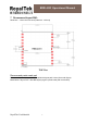
REB-4315 Operational Manual 2 Product Pictures Pin 1 3 REB-4315 Block Diagram System block diagram description: a. External antenna. b. 16 Mega bits flash memory c.
REB-4315 Operational Manual 4 REB-4315 Technical Specification Impedance:50Ω No Function Specification GPS receiver 1 Chipset SiRF Star IV, GSD4e 2 Frequency L1 1575.42MHz. 3 Code C.A. Code. 4 Channels 48 track verification channels 5 Sensitivity (Acquisition) It shall show C/No ≧ 40 dB-Hz when external power = -130dBm. 6 Cold start 35 sec (50% -130dBm Fu 0.5 ppm Tu ±2s Pu 30km) 7 Warm start 35 sec (50% -130dBm Fu 0.5 ppm Tu ±2s Pu 30km) 8 Hot start 1 sec (50% -130dBm Fu 0.
REB-4315 Operational Manual 5 Reference schematic: For example: Note: (1) Ground Planes: These pin(8、18、20、21、22) should be connect to ground. (2) Serial Interface: (Ⅰ)The TX pin is the serial output data. (Ⅲ)The RX pin is the serial input data.< UART data receive (RX)> (3) RF_IN: Connecting to the antenna has to be routed on the PCB. The transmission line must to be control impedance from RF_IN pin to the antenna or antenna connector of your choice.
REB-4315 Operational Manual Input pulse is required to start the system, and switch the operation mode to full-power mode or Hibernate mode. (7) Wakeup: Wakeup output indicate the chip states, when chip is working the output is high level. Wakeup output can control or enable the external regulator.(Ex. To control external antenna power) (8) Boot Set this pin to high for programming flash. Normal operation mode it is set to low voltage.
REB-4315 Operational Manual 7 Recommend layout PAD: Dimension:13mm*15mm*2.2mm(Tolerance:±0.2mm) TOP View Recommend paste mask pad Recommend paste mask pad is shift outside the layout pad 0.
REB-4315 Operational Manual TOP View 8 Mechanical diagram RoyalTek Confidential 8
REB-4315 Operational Manual 9 Interface document Top View Pin defined: Pin No. Name Input/ Output Description 1 NC Non connect 2 NC Non connect 3 PPS Output TM Time mark output. Output pulse timing. Characteristics Vol Max:0.4v Voh Min:1.35v (CMOS I/O run from 1.8v) Vol Max:0.4v 4 TX Output UART data transmit. Voh Min:1.35v (CMOS I/O run from 1.8v) Vil :-0.4v~0.45v 5 RX Input UART data receive. Vih :1.26v~3.6v (CMOS I/O run from 1.8v) 6 GPIO-3 Reserved Reserved.
REB-4315 Operational Manual 9 10 nRESET Input ON/OFF Input External reset input with Vil :-0.4v~0.45v internal pull-up, active Vih :1.26v~1.8v low. (CMOS I/O run from 1.8v) Power control pin. Vil :-0.4v~0.45v Need a pulse to ON or Vih :1.26v~3.6v OFF the Chip set. (CMOS I/O run from 1.8v) 11 NC Non connect 12 VCC_IN_1V8 Input 13 DR_I2C_DIO Reserved Reserved. 14 DR_I2C_SCK Reserved Reserved. 15 GPIO-2 Reserved Reserved. Single voltage supply of 1.8v. Max. 1.89v Vil :-0.
REB-4315 Operational Manual RX(CMOS I/O run from 1.8v) UART data receive (RX) TX (CMOS I/O run from 1.8v) UART data transmit (TX) RF_IN This pin receives GPS analog signal. The line on the PCB between the antenna(or antenna connector) has to be a controlled impedance line (Microstrip at 50Ω). ON_OFF (CMOS I/O run from 1.8v) Input pulse is required to start the system, and switch the operation mode to full-power mode or Hibernate mode. Wakeup(CMOS I/O run from 1.
REB-4315 Operational Manual 10.
REB-4315 Operational Manual Diff. Ref. Station ID 0000 Checksum *18 End of message termination <CR><LF> Table 3 Position Fix Indicators Value Description 0 Fix not available or invalid 1 GPS SPS Mode, fix valid 2 Differential GPS, SPS Mode, fix valid 3-5 Not Supported 6 Dead Reckoning Mode, fix valid GSA-GNSS DOP and Active Satellites Table 4 contains the values of the following example: $GPGSA, A, 3, 07, 02, 26, 27, 09, 04, 15, , , , , , 1.8,1.0,1.
REB-4315 Operational Manual Table 6 Mode 2 Value Description 1 Fix not available 2 2D 3 3D GSV-GNSS Satellites in View Table 7 contains the values of the following example: $GPGSV, 2, 1, 07, 07, 79, 048, 42, 02, 51, 062, 43, 26, 36, 256, 42, 27, 27, 138, 42*71 $GPGSV, 2, 2, 07, 09, 23, 313, 42, 04, 19, 159, 41, 15, 12, 041, 42*41 Table 7 GSV Data Format Name Example Message ID $GPGSV Total Number of Units Description GSV protocol header 2 Range 1 to 3 1 Range 1 to 3 Messages1 Messages Num
REB-4315 Operational Manual $GPRMC, 161229.487, A, 3723.2475, N, 12158.3416, W, 0.13, 309.62, 120598, ,*10 Table 8 RMC Data Format Name Message ID UTC Time Example $GPRMC Longitude hhmmss.sss A A=data valid or V=data not valid 3723.2475 N/S Indicator ddmm.mmmm N N=north or S=south 12158.3416 E/W Indicator Speed Over Ground Course Over dddmm.mmmm W 0.13 309.62 Description RMC protocol header 161229.
REB-4315 Operational Manual Name Message ID Course over rgound Reference Course over ground Reference Speed over ground Units Speed over ground Units Mode Checksum Table 9 VTG Data Format Example Units Description $GPVTG VTG protocol header 79.65 degrees Measured heading T True degrees Measured heading M Magnetic 2.69 Knots Measured speed N Knots 5.
REB-4315 Operational Manual 11. Package Specification and Order Information Shipment Method: Tape and reel SMT type with stamp holes (22 holes) 12 Contact Royaltek Contact: sales@royaltek.com Headquarter: Address:4F., No.188, Wen Hwa 2nd Rd., Kuei Shan, Tao Yuan 333, Taiwan TEL: 886-3-3960001 FAX: 886-3-3960065 Web Site: http://www.royaltek.com Web Site Customer Service: http://www.royaltek.com/contact Revision History Title REB-4315 GPS Module Doc Type User Manual Revision Date Author Number 0.