
Instructions / Assembly

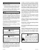


Table Of Contents
- BCE5E Unit Dimensions – Upflow – Inches (mm)
- Shipping and Packing List
- General
- Requirements
- Use of Air Handler During Construction
- Installation Clearances
- Installation
- Condensate Drain
- Duct System and Filters
- Brazing Refrigerant Lines
- Sealing the Unit
- Electrical Connections
- Blower Performance Data
- Air Flow - Cooling Blower Speed
- Checkout Procedures
- Operation
- Professional Maintenance
- Homeowner Maintenance
- Cabinet Insulation

507788-01 Issue 2007 Page 7 of 20
Condensate Drain
On units of this type, where the blower “draws” rather
than “blows” air through the coil, traps must be installed
in the condensate drain lines (primary and auxiliary,
if used). Traps prevent the blower from drawing air
through the drain lines into the air supply.
IMPORTANT
A eld-fabricated secondary drain pan, with a drain
pipe to the outside of the building, is required in all
installations over a nished living space or in any area
that may be damaged by overow from the main drain
pan. In some localities, local codes may require a
secondary drain pan for any horizontal installation.
IMPORTANT
Sloping The Unit
Make sure the unit is sloped (similar to the slope shown
in Figure 6) so that the drain pan will empty completely
without water standing in the pan.
THIS CORNER SHOULD BE 5/8" (+/- 1/8") HIGHER
THAN DRAIN CORNER
DRAIN CORNER
LEVEL PLANE
Figure 6. Sloping the Unit for Proper Drainage
Install Condensate Drain
The air handler is provided with 3/4” NPT condensate drain
connections.
On some pans, the primary and secondary drain holes
have knockouts.
Conrm primary and secondary drains are open.
IMPORTANT
1. BCE5E units are equipped with a drain pan, which
includes green (main drain) and red (secondary drain)
plugs. Unscrew the plugs to remove them before
inserting condensate drain ttings.
DRAIN PAN
RED SECONDARY
DRAIN PLUG
UNSCREW PLUGS
AND CONNECT
PROPERLY SIZED
FIELD-PROVIDED
FITTINGS AND
DRAIN LINES.
GREEN MAIN
DRAIN PLUG
Figure 7. Drain Line Connections
2. Install properly sized, eld-provided connection ttings
and connect primary drain line to the main drain pan
connection.
NOTE: When installing drain line connection ttings
to the drain pan, hand tighten the tting and use a
thread sealant. Over-tightening the ttings can split
connections on the drain pan.
3. If the secondary drain line is to be used, remove the
plug or the knockout and route the drain line so that
water draining from the outlet will be easily noticed
by the homeowner. Refer to local codes for drain trap
requirements on the secondary drain line.
Downow Application
If downow application is required, separately order a
downow conversion kit and install per kit instructions.
See Table 1 for kit information. Also use metal or class I
supply and return air plenums.
Model Kit Number
018, 024, 030 Y9658
036, 042, 048, 060 Y9659
Table 1. Downow Conversion Kits
Units installed on combustible oors in the downow
position with electric heat require a downow combustible
ooring base. See Table 2 for kit information. Install per kit
instructions.
Model Kit Number
018, 024, 030 12W95
036, 042, 048, 060 12W96
Table 2. Downow Combustible Floor Base Kits
If electric heat section with circuit breakers (ECBA25) is
installed in a BCE5E unit in a downow application, the
circuit breakers must be rotated 180° to the UP position.
See ECBA25 installation instructions for more details.
IMPORTANT