
Installation Guide

507324-01 Page 21 of 32Issue 1722
Leak Check
After gas piping is completed, carefully check all piping
connections (factory and eld installed) for gas leaks. Use
a leak detecting solution or other preferred means.
NOTE: If emergency shutoff is necessary, shut off the main
manual gas valve and disconnect the main power to the
furnace. The installer should properly label these devices.
Some soaps used for leak detection are corrosive to
certain metals. Carefully rinse piping thoroughly after
leak test has been completed. Do not use matches,
candles, ame or other sources of ignition to check for
gas leaks.
CAUTION
The furnace must be isolated by closing its individual
manual shut-off valve and disconnecting from the gas
supply system the during any pressure testing of the gas
supply system at pressures less than or equal to 1/2 psig
(3.48 kPa, 14 inches w.c.).
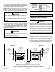
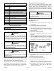
When testing pressure of gas lines, gas valve must be
disconnected and isolated. See Figure 26. Gas valves
can be damaged if subjected to pressures greater than
1/2 psig (3.48 kPa, 14 inches w.c.).
IMPORTANT
Electrical
ELECTROSTATIC DISCHARGE (ESD)
Precautions and Procedures
Electrostatic discharge can affect electronic components.
Take precautions during furnace installation and service
to protect the furnace’s electronic controls. Precautions
will help to avoid control exposure to electrostatic
discharge by putting the furnace, the control and the
technician at the same electrostatic potential. Neutralize
electrostatic charge by touching hand and all tools on
an unpainted unit surface, such as the gas valve or
blower deck, before performing any service procedure.
CAUTION
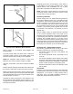
The unit is equipped with a eld make-up box on the left
hand side of the cabinet. The make-up box may be moved
to the right side of the furnace to facilitate installation. If
the make-up box is moved to the right side, clip the wire
ties that bundle the wires together. The excess wire must
be pulled into the blower compartment. Secure the excess
wire to the existing harness to protect it from damage.
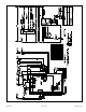
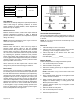
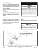
FIELD
PROVIDED
AND INSTALLED
Left Side Piping
(Standard)
Right Side Piping
(Alternate)
GROUND
JOINT
UNION
DRIP LEG
MANUAL
MAIN SHUT-OFF
VALVE
AUTOMATIC
GAS VALVE
(with manual
shut-off valve)
GROUND
JOINT
UNION
DRIP LEG
MANUAL
MAIN SHUT-OFF
VALVE
AUTOMATIC
GAS VALVE
(with manual
shut-off valve)
NOTE: BLACK IRON PIPE ONLY TO BE ROUTED INSIDE OF CABINET
Figure 27. Possible Gas Piping Congurations - Upow Applications
Figure 26.