
Installation Guide

507324-01Page 24 of 32 Issue 1722
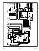
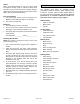
NOTE: This control is equipped with a push button switch
for diagnostic code recall. The control stores the last 5 fault
codes in non-volatile memory. The most recent fault code
is ashed rst, the oldest fault code is ashed last. There is
a 2 second pause between codes. When the push button
switch is pressed for less than 5 seconds, the control will
ash the stored fault codes when the switch is released.
The fault code history may be cleared by pressing the push
button switch for more than 5 seconds.
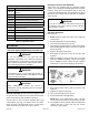
Figure 32. Integrated Control
(Automatic Hot Surface Ignition System)
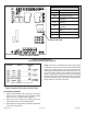
Terminal Designations
120 HUM Humidier (120 VAC)
LINE Input (120 VAC)
XFMR Transformer (120 VAC)
EAC
Electronic Air Cleaner
(120 VAC)
COOL
Blower - Cooling Speed
(120 VAC)
HEAT
Blower - Heating Speed
(120 VAC)
PARK
Dead terminals to park all speed
taps
FLAME Flame sensor
NEUTRALS Neutral Terminals (120 VAC)
3 AMP, 32 VAC FUSE
HEAT OFF DELAY JUMPER
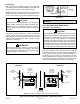
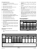
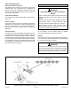
Figure 30. Condensing Unit Thermostat Designations
(Refer to Specic Thermostat and Outdoor Unit)
* Note: “R” Required on some outdoor units.
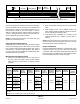
Indoor Blower Speeds
1. When the thermostat is set to “FAN ON,” the indoor
blower will run continuously on the heating speed
when there is no cooling or heating demand.
2. When the unit is running in the heating mode, the
indoor blower will run on the heating speed.
3. When there is a cooling demand, the indoor blower will
run on the cooling speed.