
Installation Guide

507324-01 Page 25 of 32Issue 1722
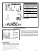
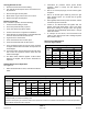
Table 7. Diagnostic Codes
Integrated Control Diagnostic Codes
LED Status Fault Description
LED Off
No power to control or control hardware fault
detected
LED On Normal operation
1 Flash Flame present with gas valve off
2 Flashes Pressure switch closed with inducer off
3 Flashes Pressure switch open with inducer on
4 Flashes High limit switch open
5 Flashes Rollout switch open
6 Flashes Pressure switch cycle lockout
7 Flashes Lockout due to no ignition
8 Flashes Lockout due to too many ame dropouts
9 Flashes Incorrect line voltage phasing
Unit Start-Up
FOR YOUR SAFETY READ BEFORE LIGHTING UNIT
Do not use this furnace if any part have been
underwater. Immediately call a licensed professional
service technician (or equivalent) to inspect the furnace
and to replace any part of the control system and any
gas control which has been underwater.
WARNING
If overheating occurs or if gas supply fails to shut off,
shut off the manual gas valve to the appliance before
shutting off electrical supply.
WARNING
Before attempting to perform any service or
maintenance, turn the electrical power to unit OFF at
disconnect switch.
CAUTION
BEFORE LIGHTING smell all around the appliance area
for gas. Be sure to smell next to the oor because some
gas is heavier than air and will settle on the oor.
The gas valve on this unit will be equipped with a gas
control switch. Use only your hand to move the switch.
Never use tools. If the switch will not turn or if the control
switch will not move by hand, do not try to repair it.
Placing the Furnace into Operation
These units are equipped with an automatic ignition
system. Do not attempt to manually light burners on these
furnaces. Each time the thermostat calls for heat, the
burners will automatically light. The ignitor does not get hot
when there is no call for heat on units with an automatic
ignition system.
If you do not follow these instructions exactly, a re
or explosion may result causing property damage,
personal injury or death.
WARNING
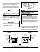
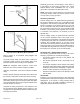
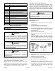
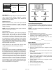
Gas Valve Operation
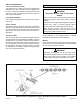
See Figure 33
1. STOP! Read the safety information at the beginning
of this section.
2. Set the thermostat to the lowest setting.
3. Turn off all electrical power to the unit.
4. This furnace is equipped with an ignition device which
automatically lights the burners. Do not try to light the
burners by hand.
5. Remove the upper access panel.
6. Move switch on gas valve to OFF. Do not force. See
Figure 33.
7. Wait ve minutes to clear out any gas. If you then
smell gas, STOP! Immediately call your gas supplier
from a neighbor’s phone. Follow the gas supplier’s
instructions. If you do not smell gas go to next step.
Figure 33.
Gas Valve Shown in “ON” Position
8. Move switch on gas valve to ON. Do not force. See
Figure 33.
9. Replace the upper access panel.
10. Turn on all electrical power to the unit.
11. Set the thermostat to desired setting.
NOTE: When unit is initially started, steps 1 through
11 may need to be repeated to purge air from gas line.
12. If the appliance will not operate, follow the instructions
“Turning Off Gas to Unit” and call your service
technician or gas supplier.