
Installation Guide

507324-01Page 26 of 32 Issue 1722
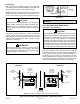
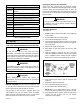
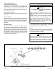
Turning Off Gas to Unit
1. Set the thermostat to the lowest setting.
2. Turn OFF all electrical power to the unit if service is to
be performed.
3. Remove the upper access panel.
4. Move switch on gas valve to OFF. Do not force.
5. Replace the upper access panel.
Failure to Operate
If the unit fails to operate, check the following:
1. Is the thermostat calling for heat?
2. Are access panels securely in place?
3. Is the main disconnect switch closed?
4. Is there a blown fuse or tripped circuit breaker?
5. Is the lter dirty or plugged? Dirty or plugged lters will
cause the limit control to shut the unit off.
6. Is gas turned on at the meter?
7. Is the manual main shut-off valve open?
8. Is the internal manual shut-off valve open?
9. Is the unit ignition system in lock out? If the unit locks
out again, call the service technician to inspect the unit
for blockages.
10. Is pressure switch closed? Obstructed ue will cause
unit to shut off at pressure switch. Check ue and
outlet for blockages.
11. Are ame rollout switches tripped? If ame rollout
switches are tripped, call the service technician for
inspection.
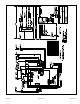
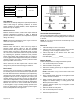
Heating Sequence of Operation
See Figure 34
1. When thermostat calls for heat, combustion air blower
starts.
2. Combustion air pressure switch proves blower
operation. Switch is factory set and requires no
adjustment.
3. After a 15 second pre-purge, the hot surface ignitor
energizes.
4. After a 20 second ignitor warm-up period, the gas
valve solenoid opens. A 4 second trial for ignition
period begins.
5. Gas is ignited, ame sensor proves the ame, and the
combustion process continues.
6. If ame is not detected after rst ignition trial, the
ignition control will repeat steps 3 and 4 four more
times before locking out the gas valve. The ignition
control will then automatically repeat steps 1 through
6 after 60 minutes.
7. To interrupt the 60 minute, move thermostat from
“Heat” to “OFF” then back to “Heat”. Heating sequence
then restarts at step 1.
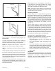
Gas Pressure Adjustment
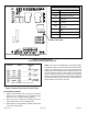
Gas Flow (Approximate)
Table 8.
Gas Meter Clocking Chart
Unit
Seconds for One Revolution
Natural LP
1 cu ft
Dial
2 cu ft
Dial
1 cu ft
Dial
2 cu ft
Dial
-045 80 160 200 400
-070 55 110 136 272
-090 41 82 102 204
-110 33 66 82 164
-135 27 54 68 136
Natural - 1000 btu/cu ft LP - 2500 btu/cu ft
Manifold Pressure and Line Pressure at Various Altitudes
Capacity
Manifold Pressure (in. w.c.)
1
Line Pressure (in. w.c.)
0 - 2000 ft. 2001 - 4500 ft. 4501 - 7500 ft. 7501 - 10000 ft. Minimum Max.
Nat.
Gas
LP
Gas
2
Nat.
Gas
LP
Gas
2
Nat.
Gas
LP
Gas
2
Nat.
Gas
3
LP
Gas
2
Nat.
Gas
LP
Gas
2
Nat. &
LP
045
3.5 10.0
3.2 10.0 3.0 10.0
3.5 10.0 4.5 11.0 13.0
070 3.2 10.0 2.8 10.0
090 3.2 10.0 2.7 9.6
110 3.5 10.0 3.0 9.6
135 3.5 10.0 2.9 9.6
1
Manifold pressure adjustments based on 1020 Btu/ft
3
gas for natural and 2500 Btu/ft3 gas for LP (corrected to standard conditions).
Consult local utility for actual local heating value.
2
A natural to LP/Propane gas conversion Orice Kit is required to convert this unit. Refer to kit instructions for conversion procedure.
3
A high altitude natural Orice Kit is required.
Table 9.