
Installation Guide

507324-01 Page 27 of 32Issue 1722
Furnace should operate at least 5 minutes before checking
gas ow. Determine time in seconds for two revolutions of
gas through the meter. (Two revolutions assures a more
accurate time.) Divide by two and compare to time in
Table 8. If manifold pressure matches Table 9 and rate is
incorrect, check gas orices for proper size and restriction.
Remove temporary gas meter if installed.
NOTE: To obtain accurate reading, shut off all other gas
appliances connected to meter.
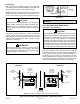
Supply Pressure Measurement
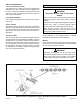
A threaded plug on the inlet side of the gas valve provides
access to the supply pressure tap. Remove the threaded
plug, install a eld provided barbed tting and connect
a manometer to measure supply pressure. See Table 9
for proper line pressure. Replace the threaded plug after
measurements have been taken.
Manifold Pressure Measurement
1. Remove the threaded plug from the outlet side of
the gas valve and install a eld provided barbed
tting. Connect to a manometer to measure manifold
pressure.
2. Start unit and allow 5 minutes for unit to reach steady
state.
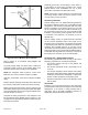
3. While waiting for the unit to stabilize, observe the
ame. Flame should be stable and should not lift from
burner. Natural gas should burn blue.
4. After allowing unit to stabilize for 5 minutes, record
manifold pressure and compare to value given in
Table 9.
NOTE: Shut unit off and remove manometer as soon as an
accurate reading has been obtained. Take care to remove
barbed tting and replace threaded plug.
Proper Combustion
Furnace should operate a minimum 15 minutes with correct
manifold pressure and gas ow rate before checking
combustion. Take combustion sample beyond the ue out
let and compare to the tables below. The maximum carbon
monoxide reading should not exceed 100 ppm.
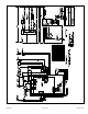
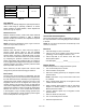
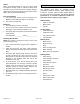
Figure 34. Integrated Ignition Control
Demand
15
ON
OFF
CAI
35
1
Pre-Purge
Ignitor Warm-up
Blower
“On” Delay
Post
Purge
5 SEC80
Ignitor
Gas Valve
Indoor Blower
39
Trial for
Ignition
Blower on time will be 45 seconds after gas valve is energized. Blower off time will depend on “OFF TIME” Setting.
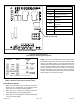
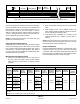
Orice Kits and Pressure Switch Kits at Various Altitudes
Capacity
0 - 4500 ft. 4501 - 7500 ft. 7501 - 10000 ft.
Pressure
1
Switch Kit
Natural
to LP /
Propane
Orice Kit
LP /
Propane
to Natural
Orice Kit
Pressure
1
Switch Kit
Natural
to LP /
Propane
Orice Kit
LP /
Propane
to Natural
Orice Kit
Pressure
1
Switch Kit
Natural
Orice Kit
LP /
Propane
Orice Kit
045
As Shipped
(-0.65” w.c.)
11K50
2
(0.034”)
73W80
2
(0.063”)
80W52
(-0.60” w.c.)
11K50
2
(0.034”)
73W80
2
(0.063”)
80W51
(-0.55” w.c.)
51W01
(0.055”)
11K45
2
(0.032”)
070
As Shipped
(-0.68” w.c.)
80W52
(-0.60” w.c.)
80W51
(-0.55” w.c.)
090
As Shipped
(-0.65” w.c.)
80W52
(-0.60” w.c.)
80W51
(-0.55” w.c.)
110
As Shipped
(-0.68” w.c.)
80W57
(-0.65” w.c.)
80W52
(-0.60” w.c.)
135
As Shipped
(-0.65” w.c.)
80W52
(-0.60” w.c.)
80W51
(-0.55” w.c.)
1
Minimum allowable set points for this altitude range. Application of a Pressure Switch with lower set point (less negative / closer to zero) is not
permitted.
2
Kit contains burner orices and gas valve regulator spring(s).
Table 10.