INSTALLATION INSTRUCTIONS A95DF2V & 95G2DFV Warm Air Gas Furnace / Downflow Air Discharge Direct Vent & Non-Direct Vent This manual must be left with the homeowner for future reference. This is a safety alert symbol and should never be ignored. When you see this symbol on labels or in manuals, be alert to the potential for personal injury or death. Table of Contents Unit Dimensions...........................................................2 Parts Arrangement..............................................
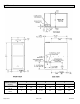
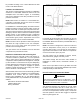
Unit Dimensions A95DF2V / 95G2DFV Capacity A B C in. mm in. mm in.
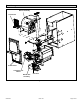
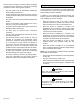
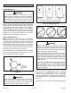
Parts Arrangement Blower Assembly Control Box Access Panel Combustion Air Inducer Burner Box Assembly Gas Valve Figure 1.
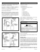
Gas Furnace Shipping and Packing List This Category IV gas furnace is shipped ready for installation in the downflow position. Package 1 of 1 contains: The furnace is equipped for installation in natural gas applications. A conversion kit (ordered separately) is required for use in LP/propane gas applications. 1 - Bag assembly containing the following: 1 - Assembled Gas Unit 1 - Snap bushing 1 - Snap Plug This unit can be installed as either a Direct Vent or a NonDirect Vent gas central furnace.
be provided according to the current National Fuel Gas Code or CSA-B149 standard. Locations and Clearances This furnace is CSA International certified for installation clearances to combustible material as listed on the unit nameplate and in the table in Figure 14. Accessibility and service clearances must take precedence over fire protection clearances. NOTE: When furnace is installed on a combustible floor, a downflow combustible flooring base must be installed between the furnace and the floor.
However, these units may be used for heating of buildings or structures under construction in the US if the following conditions are met to ensure proper operation: • The vent system must be permanently installed per these installation instructions. • A room thermostat must control the furnace. The use of fixed jumpers that will provide continuous heating is not allowed. • The return air duct must be provided and sealed to the furnace.
Combustion, Dilution & Ventilation Air If this unit is installed as a Non-Direct Vent Furnace, follow the guidelines in this section. NOTE: In Non-Direct Vent Installations, combustion air is taken from indoors and flue gases are discharged outdoors. the National Fuel Gas Code (ANSI-Z223.1/NFPA 54). This reprinted material is not the complete and official position of ANSI on the referenced subject, which is represented only by the standard in its entirely.
containing the furnace, the return air must be handled by ducts which are sealed to the furnace casing and which terminate outside the space containing the furnace. This is especially important when the furnace is mounted on a platform in a confined space such as a closet or small equipment room. Even a small leak around the base of the unit at the platform or at the return air duct connection can cause a potentially dangerous negative pressure condition.
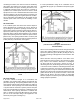
Ventilation Louvers Roof Terminated Exhaust Pipe Inlet Air (Minimum 12 in. (305mm) above Attic Floor) *Intake Debris Screen (Provided) Furnace * See Maximum Vent Lengths table NOTE: The inlet and outlet air openings shall each have a free area of at least one square inch per 4,000 Btu (645mm2 per 1.17kW) per hour of the total input of all equipment in the enclosure. Figure 7. Equipment in Confined Space - All Air from Outside (All Air Through Ventilated Attic) Figure 9.
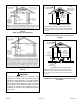
Installation Setting Equipment WARNING Do not install the furnace on its front, back or in the horizontal position. See Figure 13. Do no connect the return air ducts to the back of the furnace. Doing so will adversely affect the operation of the safety control devices, which could result in personal injury or death. Figure 12. Setting Equipment Select a location that allows for the required clearances that are listed on the unit nameplate.
Top 0 * Front 0 Back 0 Sides 0† Vent 0 Floor NC‡ Figure 15. Installation on Combustible Flooring 1. When unit is installed on a combustible floor, a downflow combustible flooring base must be installed between the furnace and the floor. The base must be ordered separately. See Table 2 for opening size to cut in floor. * Front clearance in alcove installation must be 24 in. (610 mm). Maintain a minimum of 24 in. (610 mm) for front service access.
2. After opening is cut, set the combustible flooring base into opening. 3. Check fiberglass strips on the combustible flooring base to make sure they are properly glued and positioned. 4. Lower supply air plenum into the combustible flooring base until plenum flanges seal against fiberglass strips. NOTE: Be careful not to damage fiberglass strips. Check for a tight seal. 5. Set the furnace over the plenum. 6. Ensure that the seal between the furnace and plenum is adequate. Figure 18.
furnace is installed. The furnace access panel must always be in place when the furnace is operating and it must not allow leaks into the supply air duct system. Return Air Plenum NOTE: Return air must not be drawn from a room where this furnace, or any other gas-fueled appliance (i.e., water heater), or carbon monoxide-producing device (i.e., wood fireplace) is installed. When return air is drawn from a room, a negative pressure is created in the room.
vent (exhaust) system. When bonding the vent system to the furnace, use ULC S636 approved One-Step Transition Cement to bond the pipe to the flue collar. In addition, the first three feet of vent pipe from the furnace flue collar must be accessible for inspection. 1. Measure and cut vent pipe to desired length. Table 5 lists the available exhaust termination kits. All vent terminations are PVC. Joint Cementing Procedure 2. Debur and chamfer end of pipe, removing any ridges or rough edges.
during assembly (but not after pipe is fully inserted) to distribute cement evenly. Do not turn ABS or cellular core pipe. NOTE: Assembly should be completed within 20 seconds after last application of cement. Hammer blows should not be used when inserting pipe. 8. 9. After assembly, wipe excess cement from pipe at end of fitting socket. A properly made joint will show a bead around its entire perimeter. Any gaps may indicate an improper defective assembly due to insufficient solvent.
Vent Piping Guidelines This gas furnace can be installed as either a Non-Direct Vent or a Direct Vent gas central furnace. NOTE: In non-Direct Vent installations, combustion air is taken from indoors and flue gases are discharged outdoors. In Direct Vent installations, combustion air is taken from outdoors and flue gases are discharged outdoors. Intake and exhaust pipe sizing - Size pipe according to Table 6 and Table 7A through Table 7C. Table 6 lists the minimum vent pipe lengths permitted.
Use the following steps to correctly size vent pipe diameter. 1 Furnace capacity? 045, 070, 090, 110 2 Which termination? Standard or Concentric? See Table 5 3 Which needs most elbows? Intake or Exhaust? 4 How many? 5 Desired pipe size? 6 What is the altitude? 7 Use Table 7 to find max pipe length. 2”, 2-1/2” or 3” Figure 22.
A95DF2V & 95G2DFV Maximum Allowable Intake or Exhaust Vent Length in Feet Standard Termination at Elevation 0 - 4,500 ft 2-1/2" Pipe Capacity 2nd Pipe Capacity 3" Pipe Capacity Number of 90° Elbows Used 045 070 090 110 045 070 090 110 045 070 090 110 1 66 51 29 9 100 100 78 43 123 122 103 103 2 3 4 5 6 7 8 9 10 61 56 51 46 41 36 31 26 21 46 41 36 31 26 21 16 11 6 24 19 14 9 95 95 73 38 118 90 90 68 33 113 85 85 63 28 108 80 80 58 23 103 75 75 53 18 98 n/a 70 70 48 13 93 65 6
A95DF2V & 95G2DFV Maximum Allowable Intake or Exhaust Vent Length in Feet Concentric Termination at Elevation 0 - 4,500 ft 2-1/2" Pipe Capacity 2nd Pipe Capacity 3" Pipe Capacity Number of 90° Elbows Used 045 070 090 110 045 070 090 110 045 070 090 110 1 58 43 27 7 90 90 74 39 106 106 99 99 2 3 4 5 6 7 8 9 10 53 48 43 38 33 28 23 18 13 38 33 28 23 18 13 22 17 12 7 85 85 69 34 101 80 80 64 29 96 75 75 59 24 91 70 70 54 19 86 65 65 49 14 81 n/a 60 60 44 9 76 55 55 39 71 n/a n/
A95DF2V & 95G2DFV Maximum Allowable Exhaust Vent Length Using Ventilated Attic or Crawl Space for Intake Air in Feet Standard Termination at Elevation 0 - 10,000 ft 2-1/2" Pipe Capacity 2nd Pipe Capacity Number of 90° Elbows Used 045 070 090 1 56 41 2 3 4 5 6 7 8 9 10 51 46 41 36 31 26 21 16 11 36 31 26 21 16 11 6 1 n/a 045 070 090 110 045 070 090 110 24 85 85 63 28 103 102 83 83 19 14 9 4 80 75 70 65 60 55 50 45 40 80 75 70 65 60 55 50 45 40 58 53 48 43 38 33 28 23 18 23 18
Figure 24. Typical Intake Pipe Connections (Direct Vent Applications) Intake Piping This furnace may be installed in either direct vent or nondirect vent applications. In non-direct vent applications, when intake air will be drawn into the furnace from the surrounding space, the indoor air quality must be considered. Guidelines listed in Combustion, Dilution and Ventilation Air section must be followed. 2.
Position termination according to location given in Figure 28 or Figure 29. In addition, position termination so it is free from any obstructions and 12” above the average snow accumulation. Roof Terminated Exhaust Pipe Ventilation Furnace Louvers (Crawl Space) Coupling or 3 in. to 2 in. Transition (Field Provided) At vent termination, care must be taken to maintain protective coatings over building materials (prolonged exposure to exhaust condensate can destroy protective coatings).
Maximum Allowable Exhaust Vent Pipe Length (in ft.) without Insulation in Unconditioned Space for Winter Design Temperatures Winter Design Temperatures1 ºF (ºC) Unit Input Size Vent Pipe Diameter 045 PVC 32 to 21 (0 to -6) 20 to 1 (-7 to -17) 0 to -20 (-18 to -29) 070 2 PP PVC 090 2 PP PVC 110 2 PP PVC 2 PP 2 in. 21 18 33 30 46 42 30 30 2-1/2 in. 16 N/A 26 N/A 37 N/A 36 N/A 3 in. 12 12 21 21 30 30 29 29 2 in. 11 9 19 17 28 25 27 24 2-1/2 in.
VENT TERMINATION CLEARANCES FOR NON-DIRECT VENT INSTALLATIONS IN THE US AND CANADA INSIDE CORNER DETAIL G H A D E B L Fixed Closed Operable F B B C B K AREA WHERE TERMINAL IS NOT PERMITTED AIR SUPPLY INLET VENT TERMINAL M J A B I Fixed Closed Operable US Installations1 A= Clearance above grade, veranda, porch, deck or balcony B= Clearance to window or door that may be opened C= Clearance to permanently closed window D= Vertical clearance to ventilated soffit located above the ter
VENT TERMINATION CLEARANCES FOR DIRECT VENT INSTALLATIONS IN THE USA AND CANADA INSIDE CORNER DETAIL G H A D E B L Fixed Closed Operable F B B C Operable B A B M K J AREA WHERE TERMINAL IS NOT PERMITTED AIR SUPPLY INLET VENT TERMINAL I Fixed Closed US Installations1 A= Clearance above grade, veranda, porch, deck or balcony B= Clearance to window or door that may be opened C= Clearance to permanently closed window D= Vertical clearance to ventilated soffit located above the terminal
Details of Intake and Exhaust Piping Terminations for Direct Vent Installations NOTE: Care must be taken to avoid recirculation of exhaust back into intake pipe. NOTE: In Direct Vent installations, combustion air is taken from outdoors and flue gases are discharged to outdoors. NOTE: Flue gas may be slightly acidic and may adversely affect some building materials.
Figure 33. Flush Mount Side Wall Termination 6. On field supplied terminations, a minimum distance between the end of the exhaust pipe and the end of the intake pipe without a termination elbow is 8” and a minimum distance of 6” with a termination elbow. See Figure 38. 7. If intake and exhaust piping must be run up a side wall to position above snow accumulation or other obstructions, piping must be supported every 24” (610 mm) as shown in Figure 38.
Figure 36. Optional Vent Termination for Multiple Unit Installation of Direct Vent Wall Termination Kit Figure 34. Direct Vent Concentric Rooftop Termination Figure 35. Direct Vent Concentric Wall Termination Figure 37.
FIELD FABRICATED WALL TERMINATION NOTE − FIELD−PROVIDED REDUCER MAY BE REQUIRED TO ADAPT LARGER VENT PIPE SIZE TO TERMINATION 2” (51mm) 3” (76mm) Vent Pipe Vent Pipe D D B C1 A B Intake Elbow C2 A STRAIGHT APPPLICATION * WALL SUPPORT D E D E B B A C1 EXTENDED APPLICATION A C2 A− Minimum clearance above grade or average snow accumulation 12” (305 mm) 12” (305 mm) B− Maximum horizontal separation between intake and exhaust 6” (152 mm) 6” (152 mm) C1 -Minimum from end of exhaust t
Details of Exhaust Piping Terminations for NonDirect Vent Applications Exhaust pipe may be routed either horizontally through an outside wall or vertically through the roof. In attic or closet installations, vertical termination through the roof is preferred. Figure 39 through Figure 42 show typical terminations. 1. Exhaust piping must terminate straight out or up as shown. The termination pipe must be sized as listed in Table 9.
Exhaust through Crawl Space Vent Option All 33” condensing gas furnaces (92%+) are now approved to be vented down through a crawl space. Ensure a vent pipe drain kit, 51W18 (USA) or 15Z70 (Canada), is used as directed through the floor joists and into the crawl space. See the following figures. Exhaust from Furnace To Termination Consult the vent tables for vent lengths and approved materials.
Condensate Piping This unit is designed for either right or left side exit of condensate piping in downflow applications. Refer to Figure 46 for condensate trap locations. NOTE: Vinyl tubing may be used for condensate drain. Tubing must be 1-1/4” OD x 1” ID and should be attached to the drain on the trap using a hose clamp. 5. NOTE: If necessary the condensate trap may be installed up to 5 feet away using PVC pipe from the furnace. Piping from furnace must slope down a minimum of 1/4” per ft. toward trap.
Figure 48. Evaporator Coil Using a Separate Drain Figure 50. Condensate Trap with Optional Overflow Switch CAUTION When combining the furnace and evaporator coil drains together, the A/C condensate drain outlet must be vented to relieve pressure in order for the furnace pressure switch to operate properly. Figure 49.
Optional Condensate Drain Connection Adapter 3/4 inch slip X 3/4 inch mpt (not furnished) 90° Street Elbow 3/4 inch PVC (not furnished) Adapter 3/4 inch slip X 3/4 inch mpt (not furnished) Condensate Drain Connection In Unit 90° Street Elbow 3/4 inch PVC ( furnished) 1 (25 mm) Min. 2 (50 mm) Max.
Gas Piping IMPORTANT Compounds used on threaded joints of gas piping must be resistant to the actions of liquified petroleum gases. CAUTION If a flexible gas connector is required or allowed by the authority that has jurisdiction, black iron pipe shall be installed at the gas valve and extend outside the furnace cabinet. The flexible connector can then be added between the black iron pipe and the gas supply line.
Figure 53. Gas Pipe Capacity - FT³/HR (kL/HR) Nominal Iron Pipe Size inches (mm) Internal Diameter - inches (mm) Length of Pipe - feet (m) 10 20 30 (3.048) (6.096) (9.144) 40 50 60 70 80 90 100 (12.192) (15.240) (18.288) (21.336) (24.384) (27.432) (30.480) 1/2 .622 175 120 97 82 73 66 61 57 53 50 (12.7) (17.799) (4.96) (3.40) (2.75) (2.32) (2.07) (1.87) (1.73) (1.61) (1.50) (1.42) 3/4 .824 360 250 200 170 151 138 125 118 110 103 (19.05) (20.930) (10.
1. Electrical ELECTROSTATIC DISCHARGE (ESD) The power supply wiring must meet Class I restrictions. Protected by either a fuse or circuit breaker, select circuit protection and wire size according to unit nameplate. NOTE: Unit nameplate states maximum current draw. Maximum over current protection allowed is shown in Table 11. Precautions and Procedures CAUTION Electrostatic discharge can affect electronic components.
Indoor Blower Speeds 1. When the thermostat is set to “FAN ON,” the indoor blower will run continuously at approximately 50% of the second stage cooling speed when there is no cooling or heating demand. 2. When this unit is running in the heating mode, the indoor blower will run on the heating speed designated by the positions of DIP switches 1 (A,B,C,D) of the HEAT jumper plug. See Figure 57. 3.
Electronic Air Cleaner Terminals are provided on the integrated ignition/blower control board for connection of a 120-volt electronic air cleaner. The “ACC” terminal is energized whenever the thermostat calls for heat, cooling, or continuous blower. See furnace wiring diagram for specific connection information. Variable Speed Features This furnace is equipped with a variable speed circulation air blower motor that will deliver a constant airflow within a wide range of external static pressures.
Sequence of Operation Cooling Heating On a call for heat from the room thermostat, the control board performs a 1 second self check. Upon confirmation that the pressure switch contacts are in an open position, the control energizes the combustion blower on high speed. The control then checks for adequate combustion air by making sure the low-fire pressure switch contacts are closed.
Connect the desired speed tap to the “EAC” terminal and the neutral tap to the neutral terminal on the ignition control (refer to the furnace wiring diagram). The ignition control will control the motor’s operation, including a nominal 20 second “on” delay with a call for heat and a nominal 180 second “off” delay when the thermostat is satisfied. It will also operate the motor on a call for cooling, with no “on” or “off” delays.
Figure 58.
NOTES: 1. PRESS AND RELEASE FAULT CODE HISTORY BUTTON TO DISPLAY FAULT CODES. TO ERASE CODES, PRESS AND HOLD BUTTON IN FOR MORE THAN 5 SECONDS 2. IF ANY OF THE ORIGINAL WIRE AS SUPPLIED WITH THE FURNACE MUST BE REPLACED, IT MUST BE REPLACED WITH WIRING MATERIAL HAVING A TEMP. RATING OF AT LEAST 90°c. 3. PROPER POLARITY MUST BE OBSERVED FOR FIELD LINE VOLTAGE SUPPLY; IGNITION CONTROL WILL LOCK OUT IF POLARITY IS REVERSED. 4.
Testing for Proper Venting and Sufficient Combustion Air for Non-Direct Vent Applications 1. Seal any unused openings in the venting system. 2. Failure to follow the steps outlined below for each appliance connected to the venting system being placed into operation could result in carbon monoxide poisoning or death. Visually inspect the venting system for proper size and horizontal pitch.
Unit Start-Up FOR YOUR SAFETY READ BEFORE OPERATING 2. Set the thermostat to initiate a heating demand. 3. Allow the burners to fire for approximately 3 minutes. 4. Adjust the thermostat to deactivate the heating demand. 5. Wait for the combustion air inducer to stop. Set the thermostat to initiate a heating demand and again allow the burners to fire for approximately 3 minutes. 6. Adjust the thermostat to deactivate the heating demand and wait for the combustion air inducer to stop.
11. Set the thermostat to desired setting. NOTE: When unit is initially started, steps 1 through 11 may need to be repeated to purge air from gas line. 12. If the appliance will not operate, follow the instructions “Turning Off Gas to Unit” and call your service technician or gas supplier. one turn, connect a piece of 5/16” tubing and connect a manometer to measure supply pressure. NOTE: Shut unit off and remove manometer as soon as an accurate reading has been obtained.
Capacity Natural to LP/ Propane High Altitude Natural Burner Orifice Kit High Altitude LP/ Propane Burner Orifice Kit 0 - 7500 ft (0 - 2286m) 7501 - 10000 ft (2286 - 3048m) 7501 - 10000 ft (2286 - 3048m) High Altitude Pressure Switch 4501 - 7500 ft (1371 - 2286m) 7501 - 10000 ft (2286 - 3048m) 14A47 14A50 14A55 14A56 14A54 14A53 14A46 14A51 045 070 11K48 090 *51W01 11K47 110 *Conversion requires installation of a gas valve manifold spring which is provided with the gas conversion kit.
Blower Performance Model Temp Rise High Fire 35 - 65 A95DF2V045B12S 95G2DF045BV12 A95DF2V070B16S 95G2DF070BV16 Setting “C” Setting “B” Setting “A” + 735 830 1015 1210 Normal 680 750 930 1070 - 625 695 835 1000 + 705 780 975 1110 Normal 655 730 890 1055 - 595 670 790 960 Cooling Stage Speed Adjustment Setting “D” Setting “C” Setting “B” + 895 1050 1210 1360 2nd Stage Normal 805 965 1105 1250 - 735 865 1000 1130 Cooling CFM @ 0 - 0.8” w.c.
Model A95DF2V090C20S 95G2DF090CV20 A95DF2V090C20S Speed Adjustment High Fire 35 - 65 + 1395 1555 1695 1825 Normal 1275 1395 1585 1670 Setting “B” Setting “A” 1145 1265 1405 1525 Low Fire 20 - 50 1130 1230 1365 1475 Normal 1040 1130 1250 1340 - 910 1025 1130 1210 Cooling Stage Speed Adjustment Setting “D” Setting “C” Setting “B” Setting “A” + 1335 1600 1750 1980 Normal 1225 1450 1630 1830 - 1120 1270 1450 1660 + 955 1115 1265 1450 Normal 855 100
3. Service Check amp-draw on the blower motor with the blower compartment access panel in place. Motor Nameplate__________Actual__________ WARNING Winterizing and Condensate Trap Care 1. Turn off power to the furnace. ELECTRICAL SHOCK, FIRE, OR EXPLOSION HAZARD. 2. Have a shallow pan ready to empty condensate water. Failure to follow safety warnings exactly could result in dangerous operation, serious injury, death or property damage. 3.
16. Remove screws along vestibule sides and bottom which secure vestibule panel and heat exchanger assembly to cabinet. Remove two screws from blower rail which secure bottom heat exchanger flange. Remove heat exchanger from furnace cabinet. 17. Back wash heat exchanger with soapy water solution or steam. If steam is used it must be below 275°F (135°C). 18. Thoroughly rinse and drain the heat exchanger. Soap solutions can be corrosive. Take care to rinse entire assembly. 19.
Planned Service A service technician should check the following items during an annual inspection. Power to the unit must be shut off for safety. Operating performance - Unit must be observed during operation to monitor proper performance of the unit and the vent system. Fresh air grilles and louvers (on the unit and in the room where the furnace is installed) - Must be open and unobstructed to provide combustion air.
Requirements for Commonwealth of Massachusetts Modifications to NFPA-54, Chapter 10 4. Revise NFPA-54 section 10.8.