
Installation Guide


507052-04 Page 9 of 53Issue 1727
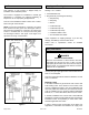
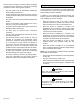
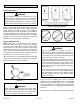
Figure 7. Equipment in Conned Space - All Air from
Outside
(All Air Through Ventilated Attic)
Figure 8. Equipment in Conned Space - All Air from
Outside
If this unit is being installed in an application with
combustion air coming in from a space serviced by an
exhaust fan, power exhaust fan, or other device which
may create a negative pressure in the space, take care
when sizing the inlet air opening. The inlet air opening
must be sized to accommodate the maximum volume
of exhaust air as well as the maximum volume of
combustion air required for all gas appliances serviced
by this space.
WARNING
Ventilation Louvers
Inlet Air
(Minimum 12 in.
(305mm) above
Attic Floor)
Roof Terminated
Exhaust Pipe
Furnace
*Intake Debris
Screen
(Provided)
* See Maximum Vent Lengths table
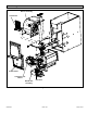
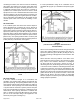
NOTE: The inlet and outlet air openings shall each have a
free area of at least one square inch per 4,000 Btu (645mm
2
per 1.17kW) per hour of the total input of all equipment in the
enclosure.
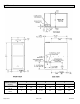
Figure 9. Equipment in Conned Space
(Inlet Air from Ventilated Attic and Outlet Air to
Outside)
Roof Terminated
Exhaust Pipe
Furnace
Ventilation
Louvers
(Crawl Space)
*Intake Debris Screen Provided
Inlet Air
Minimum
12 in. (305mm)
above Crawl
Space Floor
Coupling or
3 in. to 2 in.
Transition
(Field Provided)
* See Maximum Vent Lengths table
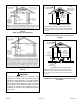
NOTE: The inlet and outlet air openings shall each have a
free area of at least one square inch per 4,000 Btu (645mm
2
per 1.17kW) per hour of the total input of all equipment in the
enclosure.
Figure 10. Equipment in Conned Space
(Inlet Air from Ventilated Crawl Space and Outlet Air
to Outside)