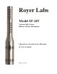
Royer Labs Model SF-24V Vacuum Tube, Stereo Ribbon Velocity Microphone Operation Instructions Manual & User Guide Made in U.S.A.
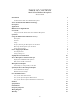
TABLE OF CONTENTS Model SF-24V Ribbon Microphone Revised 2009 Introduction 3 SF-24V Vacuum Tube Stereo Ribbon Microphone Active & Vacuum Tube Ribbon Technology Description Applications Ribbons in the Digital World User Guide 3 3 4 4 5 5 Using the SF-24V Vacuum Tube Stereo Ribbon Microphone Operation Using the RSM-24 Shock Mount Accessory 5 6 7 Description Features Usage Properly Inserting the Microphone into the Shock Removing the Microphone from the Shock Connecting the SF-24 Power Supply Input
Introduction SF-24V Vacuum Tube Stereo Ribbon Microphone Congratulations on your purchase of a Royer Labs model SF-24V vacuum tube stereo ribbon microphone. The SF-24V is a handcrafted precision instrument, capable of delivering superior sound quality and exceptional performance. The SF-24V represents a new level of performance for ribbon microphones, combining sophisticated technological advancements with old-world craftsmanship.
Description The SF-24V vacuum tube stereo coincident ribbon microphone is the only microphone of its kind available, combining high audio performance with outstanding separation and imaging. It is a modern ribbon design, with no audible diffraction effects or cavity resonance.
Although spaced microphones can produce similar stereophonic results, such recordings when summed to mono can suffer from “comb filter” effects: peaks and dips in the frequency response. When the SF-24V is used for M-S recording, the feeling of space changes but the sonic quality does not. For more detailed information on the M-S technique, see the chapter Recording Techniques: Mid-Side (M-S) Recording in this manual.
lifting the Pin-1 connection from either connector (preferably done at the input amplifier or patch bay) will usually cure the problem. 3. Be certain that the input channel fader or volume control is set to minimum before plugging in any microphone. Preamplifier gain trim should be set to minimum. Plug the microphone in and activate the power switch. The microphone’s electronics will stabilize in a few minutes but it may take up to ten minutes for optimum noise performance to be fully realized. 4.
5. Avoid dropping the microphone. An accidental fall to a hard surface could stretch one or both ribbons and, depending on the nature of the fall, possibly necessitating a complete overhaul of the microphone. Using the RSM-24 Shock Mount Accessory Description Your SF-24V is supplied with a Royer RSM-24 suspension type shock-mount accessory designed specifically for this microphone.
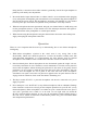
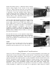
Hold the mic by placing the transducer (ribbon element) end in the palm of one hand. While holding the shock mount in the other hand, gently insert the microphone's base into the upper tube first. Be sure that the logo on the microphone aligns itself with the slot in the upper support tube as you feed the mic through. (Figure 2) Continue to feed the microphone through the upper tube and into the lower tube where it will stop when it reaches the lip at the bottom of the lower tube.
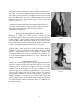
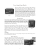
Power Supply Input Module Image 1 The power OFF/ON switch and the Power Input Module are located on the rear side of the power supply (Image 1). The Power Input Module (Image 2) serves multiple functions and is integral to the design of the power supply. It serves as a means to connect and remove the AC mains cable, it houses the AC line fuses, provides a convenient method of voltage changeover, and also serves as an RF line filter.
thumb and forefinger (Image 5). Rotate the drum so that the desired voltage appears in the window of the module (Image 6). Gently push the drum back into position and close the door. The door will snap shut when fully closed. It is important to note that changing voltage settings also requires changing the fuses to different values. The correct values can be found in the specifications section of this manual. There is more information on this subject in the "Power Input Module" section of this manual.
secondary and fall into the category of conveniences or interface capabilities (such as digital or optical outputs). A good preamplifier should sound natural, with no sign of edginess or excessive noise. Vacuum tube preamplifiers sound warm, yet wonderfully airy and transparent. Do not expect a vacuum tube preamplifier to be as quiet as a solid-state preamp, as electron emissions from tubes tend to convey more “thermal” noise than transistors.
You can perform a simple test to check for this condition (preferably done with a pair of headphones to avoid feedback). Plug one side of the stereo microphone into either preamplifier input. Listen to the output of the preamp. All should be quiet except for the mic signal. Now plug the second side into the next preamplifier input. If a noise or buzz develops, you have a ground loop. The ground loop may be very slight or more pronounced, depending on the preamp.
Unwanted magnetically induced noise (hum) can only come from external sources. Fortunately, simply repositioning a ribbon microphone often gets rid of unwanted noise. If hum is detected, the microphone is in the proximity of an alternating magnetic field. While listening (preferably with headphones) to the mic, move it around. The mic will “find” the noise source quite easily.
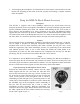
Drum Overhead & Room Position the SF-24V horizontally over the center point of the kit, two to three feet above the cymbals. For a centered snare drum, aim the Royer logo at the snare. Adjusting the height of the SF-24V by even 6-inch increments will produce dramatic variations in how the cymbals sit with the rest of the kit. Many times an overhead SF-24V is all that is needed for tomtoms and cymbals.
Piano There are several positions that will give excellent results with the piano. Start with a distance of one foot to several feet from the knee of the piano. A more direct “up front” sound will be achieved when the microphone is placed closer to the soundboard. If it is possible to remove the piano lid, the SF-24V suspended horizontally over the soundboard will give outstanding results. If the room sounds good, try positioning the mic 10 to 20 feet from the piano.
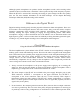
Specialized Stereo Recording Techniques Classic Blumlein Technique For many years, “coincident” microphone setups have been widely used for picking up sounds in stereo as naturally as possible. The “Blumlein” technique, named for A.D. Blumlein, involves the use of two figure-eight microphones positioned as in the sketch (see Figure 1); so that one faces left and the other faces right, at an angle of 90º (i.e., each displaced 45º from center).
element is at 90º to the performance and is the “side” microphone. If the microphone is to be mounted upside down, make the proper adjustments in your wiring orientation. If the outputs of the mid and side elements are made equal using gain controls, the stereo pickup will be similar to that of two microphones placed as a Blumlein X-Y pair, delivering a wide stereo image.
Care and Maintenance The SF-24V is a solidly built, precision instrument. Following a few commonsense rules is all that is required to ensure proper operation of this microphone. 1. To avoid transducer damage, do not expose the microphone to severe shock or vibration. If the microphone is accidentally dropped, test it to see if damage has occurred before returning it to service. Low output or a dull sound in one or both transducers would indicate a stretched ribbon. 2.
cloth, not to the microphone). Be very careful whenever working around the transducers to avoid contamination of the ribbon elements. Care for the SF-24V’s African Padouk Presentation Case The SF-24V’s handcrafted presentation case is milled from two matching pieces of African Padouk. To best protect the case, minimize direct and prolonged exposure to sunlight, heat, and moisture. As the case ages, it will take on a darker, more lustrous hue.
Specifications Acoustic Operating Principle: Electro-dynamic pressure gradient with active electronics Polar Pattern: Symmetrical Figure-8 Generating Elements: Two 1.
Polar Pattern Frequency Response 21
Wiring Diagram 22
Warranty PLEASE RETAIN YOUR ORIGINAL BILL OF SALE AS YOU WILL NEED TO PRESENT IT SHOULD YOU REQUIRE SERVICE UNDER THIS WARRANTY. TO VALIDATE THIS WARRANTY, THE REGISTRATION CARD AND A PHOTOCOPY OF THE SALES RECEIPT FROM AN AUTHORIZED ROYER DEALER MUST BE ON FILE WITH ROYER LABS. Royer Labs hereby warrants all Royer SF-series microphones with the following terms and conditions.