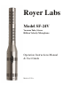
Royer Labs Model SF-24V Vacuum Tube, Stereo Ribbon Velocity Microphon Operation Instructions Manual & User Guid e e . Made in U.S.
TABLE OF CONTENTS Model SF-24V Ribbon Microphone Revised 201 Introductio SF-24V Vacuum Tube Stereo Ribbon Microphon Active & Vacuum Tube Ribbon Technolog Descriptio Application Ribbons in the Digital Worl User Guid Using the SF-24V Vacuum Tube Stereo Ribbon Microphon Operatio Power Supply Input Modul Fuse Replacemen Voltage Changeove Ampli cation Consideration Stereo Microphones and Ground Loop Equalization and Ribbon Microphone Hum, Noise and Mic Orientatio 1 1 Microphone Technique 1 General Tips fo
Introductio SF-24V Vacuum Tube Stereo Ribbon Microphon Congratulations on your purchase of a Royer Labs model SF-24V vacuum tube stereo ribbon microphone. The SF-24V is a handcrafted precision instrument, capable of delivering superior sound quality and exceptional performance. The SF-24V represents a new level of performance for ribbon microphones, combining sophisticated technological advancements with old-world craftsmanship.
Descriptio The SF-24V vacuum tube stereo coincident ribbon microphone is the only microphone of its kind available, combining high audio performance with outstanding separation and imaging. It is a modern ribbon design, with no audible diffraction effects or cavity resonance.
Although spaced microphones can produce similar stereophonic results, such recordings when summed to mono can suffer from “comb lter” effects: peaks and dips in the frequency response. When the SF-24V is used for M-S recording, the feeling of space changes but the sonic quality does not.
3. Be certain that the input channel fader or volume control is set to minimum before plugging in any microphone. Preampli er gain trim should be set to minimum. Plug the microphone in and activate the power switch. The microphone’s electronics will stabilize in a few minutes but it may take up to ten minutes for optimum noise performance to be fully realized 4. When the microphone becomes operational, bring the two channel faders to 0-dB (unity) and use the preampli er trims to set the desired level.
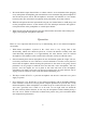
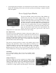
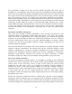
Avoid dropping the microphone. An accidental fall to a hard surface could stretch one or both ribbons and, depending on the nature of the fall, possibly necessitating a complete overhaul of the microphone. 5. Power Supply Input Modul The power OFF/ON switch and the Power Input Module are located on the rear side of the power supply (Image 1). The Power Input Module (Image 2) serves multiple functions and is integral to the design of the power supply.
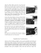
within the module. Remove the power cord and open the module door in the same manner as for accessing the fuses. The drum can be removed with a small pair of needle-nosed pliers or the thumb and fore nger (Image 5). Rotate the drum so that the desired voltage appears in the window of the module (Image 6). Gently push the drum back into position and close the door. The door will snap shut when fully closed.
Headroom, noise oor, transparency and coloration are all factors to consider in determining which preampli er is suitable for your studio or live applications. Other features are usually secondary and fall into the category of conveniences or interface capabilities (such as digital or optical outputs) A good preampli er should sound natural, with no sign of edginess or excessive noise. Vacuum tube preampli ers sound warm, yet wonderfully airy and transparent.
You can perform a simple test to check for this condition (preferably done with a pair of headphones to avoid feedback). Plug one side of the stereo microphone into either preampli er input. Listen to the output of the preamp. All should be quiet except for the mic signal. Now plug the second side into the next preampli er input. If a noise or buzz develops, you have a ground loop. The ground loop may be very slight or more pronounced, depending on the preamp.
They also incorporate toroidal impedance matching transformers, which have a natural ability to repel magnetic radiation Unwanted magnetically induced noise (hum) can only come from external sources. Fortunately, simply repositioning a ribbon microphone often gets rid of unwanted noise. If hum is detected, the microphone is in the proximity of an alternating magnetic eld. While listening (preferably with headphones) to the mic, move it around. The mic will “ nd” the noise source quite easily.
Drum Overhead & Room Position the SF-24V horizontally over the center point of the kit, two to three feet above the cymbals. For a centered snare drum, aim the Royer logo at the snare. Adjusting the height of the SF-24V by even 6-inch increments will produce dramatic variations in how the cymbals sit with the rest of the kit. Many times an overhead SF-24V is all that is needed for tomtoms and cymbals For a single point stereo room mic, position the SF-24 vertically at four to eight feet in front of the kit.
If you position the SF-24V somewhere between the soundboard and the open lid of the piano, there will be some amount of re ected sound from the lid. Careful positioning can minimize or accent lid re ections, depending on what sound you’re striving for. Choir and Orchestra An SF-24V can produce dramatically good recordings of an orchestra or choir. If possible, position the SF-24 at a height of ten feet or so and a few feet behind the conductor.
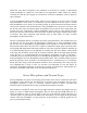
Specialized Stereo Recording Technique Classic Blumlein Techniqu For many years, “coincident” microphone setups have been widely used for picking up sounds in stereo as naturally as possible. The “Blumlein” technique, named for A.D. Blumlein, involves the use of two gure-eight microphones positioned as in the sketch (see Figure 1); so that one faces left and the other faces right, at an angle of 90 degrees (i.e.
microphone is to be mounted upside down, make the proper adjustments in your wiring orientation If the outputs of the mid and side elements are made equal using gain controls, the stereo pickup will be similar to that of two microphones placed as a Blumlein X-Y pair, delivering a wide stereo image.
Care and Maintenanc The SF-24V is a solidly built, precision instrument. Following a few commonsense rules is all that is required to ensure proper operation of this microphone 1. To avoid transducer damage, do not expose the microphone to severe shock or vibration. If the microphone is accidentally dropped, test it to see if damage has occurred before returning it to service. Low output or a dull sound in one or both transducers would indicate a stretched ribbon 2.
Care for the SF-24V’s African Padouk Presentation Case The SF-24V’s handcrafted presentation case is milled from two matching pieces of African Padouk. To best protect the case, minimize direct and prolonged exposure to sunlight, heat, and moisture. As the case ages, it will take on a darker, more lustrous hue. To maintain and beautify the case’s nish, we suggest wiping it with a thin coat of boiled linseed oil or Tung oil (available at most home improvement stores) once a year.
Speci cation Acoustic Operating Principle: Electro-dynamic pressure gradient with active electronic Polar Pattern: Symmetrical Figure- Generating Elements: Two 1.
Polar Patter Frequency Respons e n 19
Wiring Diagra m 20
Warranty PLEASE RETAIN YOUR ORIGINAL BILL OF SALE AS YOU WILL NEED TO PRESENT IT SHOULD YOU REQUIRE SERVICE UNDER THIS WARRANTY TO VALIDATE THIS WARRANTY, THE REGISTRATION CARD AND A PHOTOCOPY OF THE SALES RECEIPT FROM AN AUTHORIZED ROYER DEALER MUST BE ON FILE WITH ROYER LABS.