
Manual


Although spaced microphones can produce similar stereophonic results, such recordings when
summed to mono can suffer from “comb filter” effects: peaks and dips in the frequency response.
When the SF-24V is used for M-S recording, the feeling of space changes but the sonic quality
does not. For more detailed information on the M-S technique, see the chapter Recording
Techniques: Mid-Side (M-S) Recording in this manual.
Ribbons in the Digital World
Digital recordings benefit greatly from the properties inherent in ribbon microphones. Since A to
D converters cannot distinguish between the sound source being recorded and the complex
distortion components often associated with condenser microphones, they sometimes have
difficulty tracking the signal, resulting in ringing and edgy-sounding tracks. With ribbon
microphones, ringing is almost nonexistent due to the ribbon’s lack of distortion artifacts and
high frequency peaks. A to D converters have less difficulty tracking the ribbon generated signal,
resulting in very smooth digital recordings free of microphone-related edginess.
User Guide
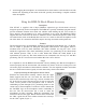
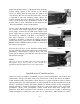
Using the SF-24V Vacuum Tube Stereo Ribbon Microphone
The head amplification system utilized in the SF-24V consists of two independently configured
military grade vacuum tube buffering circuits. Power for the tubes is supplied to the microphone
from a dedicated AC-line operated power supply that connects to the microphone through a 7-pin
microphone cable. The power supply provides a high voltage source and independent low
voltage sources for the vacuum tube's filaments. An electronic constant current source
automatically compensates for any change in the microphone's cable's length and provides the
correct voltage and current to each of the vacuum tube's heaters.
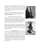
1. Always connect the microphone to the power supply before applying AC or turning the
supply on. Allow at least ten minutes of warm up time before using the microphone. This is
required to give ample time for the vacuum tubes elements to "settle."
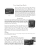
2. The stereo outputs of the SF-24V are available at the power supply through a pair of male
XLR connectors. OUTPUT 1 corresponds to the upper transducer and OUTPUT 2
corresponds to the lower transducer when the mic is held vertically. Each output is
transformer isolated and fully balanced. The SF-24V’s output configuration is as follows:
Pin-1 is a shared ground for each output connector; Pin-2 is signal hot (in-phase) and Pin-3
signal cold (reverse-phase).
3. In rare instances, the common ground connection (Pin-1) between the two output connectors
can cause a ground loop. This can occur when poorly designed preamplifiers or certain types
of patch bays and/or wiring configurations are encountered. If this condition presents itself,
5