
Operator's Manual
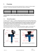
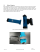
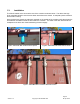
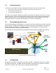
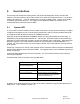
Table Of Contents

Page 10
Version 1.4
Copyright © 2019 RSAE Labs
08-Apr -2019
2. User Interface
As a security and autonomous tracking device, the GS-6C was designed to have a minimal User
Interface. The user interface of the GS-6C consists of two LEDs and a magnetic sensor. The GS-6C is
meant to be “always on”. It can be powered off by removing the battery pack. Insertion of the battery
immediately powers the device on. The majority of the operational states of the device can be
controlled remotely over-the-air from the DMC.
2.1. System LED
The “Sys LED” is used to indicate the current state of the device. During routine monitoring, the LED is
configured to blink green for one (1) second every 30 seconds. Note, the 30 second blink interval can
be configured to blink at different rates or be completely turned off.
When the GS-6C has activated the GPS/GNSS receiver, the Sys LED will blink red continuously. A
GPS/GNSS cycle generally takes between 30 – 120 seconds. When the GS-6C is communicating (or
attempting to communicate) with the DMC, the Sys LED will blink green continuously. Depending upon
the time to register on the communication network, the communications cycle takes between 1 – 5
minutes. For devices which roam onto a new cellular network, the communications cycle may take up
to 10 minutes.
Introducing a magnet in the vicinity of the magnetic sensor causes the GS-6C to acquire its GPS/GNSS
position and to initiate a report cycle with the DMC. The magnetic sensor can be disabled as part of the
device configuration
A solid red LED indicates that the device is rebooting. This occurs after the device power has been
removed and reapplied.
The table below shows a summary of the Sys LED states:
Sys LED State
Meaning
Green blink once every 30
seconds (configurable)
Routine monitoring
Continuous red blinking
Acquiring GPS/GNSS position
Continuous green blinking
Communications cycle
One second red blink
Follows magnetic sensor activation.
Results in GPS/GNSS cycle followed
by Communications cycle
Solid red LED
Device is rebooting
In addition to the states listed above, the LED can be used to indicate the approximate capacity of the
battery pack. This is detailed in Section 7.5.