
User`s manual


AX3500 Motor Controller User’s Manual 79
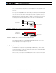
Connecting the Encoder
Specifically, the encoder module can process 250,000 counts per seconds. As discussed
in the previous section, a count is generated for each transition on the Channel A and
Channel B. Therefore the module will work with encoders outputting up to 62,500 pulses
per second.
Commercial encoders are rated by their numbers of “Pulses per Revolution” (also some-
times referred as “Cycles per Revolution). Carefully read the manufacturer’s datasheet to
understand whether this number represents the number of pulses that are output by each
channel during the course of a 360o revolution rather than the total number of transitions
on both channels during a 360o revolution. The second number is 4 times larger than the
first one.
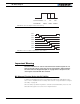
The formula below gives the pulse frequency at a given RPM and encoder resolution in
Pulses per Revolution.
Pulse Frequency in Hz = RPM / 60 * PPR * 4
Example: a motor spinning at 10,000 RPM max, with an encoder with 200 Pulses per Rev-
olution would generate:
10,000 / 60 * 200 * 4 = 133.3 kHz which is well within the 250kHz maximum supported by
the encoder module.
An encoder with a 200 Pulses per Revolutions is a good choice for most applications.
A higher resolution will cause the counter to count faster than necessary and possibly
reach the encoder module’s maximum frequency limit.
An encoder with a much lower resolution will cause speed to be measured with less preci-
sion.
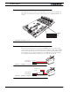
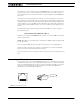
Connecting the Encoder
The Encoder module uses a widely available 8-pin RJ45 connector identical to those found
on all Ethernet devices. The connector provides 5V power to the encoders and has inputs
for the two quadrature signals from each encoder. Using multi-level signaling, it is also pos-
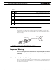
sible to share the quadrature inputs with limit switches. The figure and table below
describe the connector and its pin assignment.
1
1
8
8
FIGURE 51. Encoder connector