
Service manual


28
CDX-GT65UIW
SECTION 5
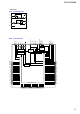
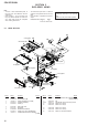
EXPLODED VIEWS
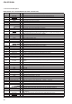
1 X-2176-199-1 LOCK ASSY
2 3-246-441-02 BUTTON (EJECT) (Z)
3 1-834-627-11 CABLE, FLEXIBLE FLAT (23 CORE)
4 3-260-247-01 CUSHION (SUB PANEL)
5 3-042-244-01 SCREW (T)
6 X-2547-696-1 PANEL (SUB) ASSY
7 X-2515-757-1 GEAR ASSY
8 A-1839-940-A MAIN BOARD, COMPLETE
9 3-376-464-11 SCREW (+PTT 2.6X6), GROUND POINT
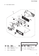
10 1-839-377-11 CONNECTION CORD FOR AUTOMOBILE
(POWER)
11 1-833-835-11 CONNECTION CORD FOR AUTOMOBILE
(SUB OUT (MONO))
12 3-264-798-01 CAP
FU301 1-532-877-11 FUSE (BLADE TYPE) (AUTO FUSE) (10A/32V)
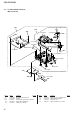
#1 7-685-792-09 SCREW +PTT 2.6X6 (S)
#2 7-685-790-01 SCREW +PTT 2.6X4 (S)
#3 7-685-793-09 SCREW +PTT 2.6X8 (S)
#4 7-685-794-09 SCREW +PTT 2.6X10 (S)
#5 7-685-134-19 SCREW +P 2.6X8 TYPE2 NON-SLIT
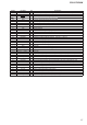
Ref. No. Part No. Description Remark Ref. No. Part No. Description Remark
Note:
• -XX and -X mean standardized parts, so
they may have some difference from the
original one.
• Items marked “*” are not stocked since
they are seldom required for routine ser-
vice. Some delay should be anticipated
when ordering these items.
• The mechanical parts with no reference
number in the exploded views are not sup-
plied.
• Color Indication of Appearance Parts Ex-
ample:
KNOB, BALANCE (WHITE) . . . (RED)
Parts Color Cabinet’s Color
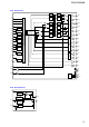
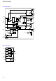
5-1. MAIN SECTION
The components identifi ed by mark 0
or dotted line with mark 0 are critical for
safety.
Replace only with part number specifi ed.
not supplied
not supplied
(SUB board)
not supplied
FU301
not supplied
not supplied
not supplied
not supplied
#1
#1
#1
#3
#4
#5
#5
#3
#4
#4
#2
#1
A
B
B
1
2
3
4
5
6
7
5
9
10
A
D
D
C
C
8
front panel section
MG-101PM-188
11
12
#3