
Service manual


CDX-GT65UIW
7
SECTION 3
DISASSEMBLY
• This set can be disassembled in the order shown below.
3-1. DISASSEMBLY FLOW
Note: Follow the disassembly procedure in the numerical order given.
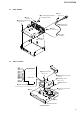
3-2. COVER
3-2. COVER
(Page 7)
3-3. PANEL (SUB) BLOCK
(Page 8)
3-4. CD MECHANISM DECK (MG-101PM-188)
(Page 8)
3-5. MAIN BOARD
(Page 9)
SET
3-6. SERVO BOARD
(Page 9)
3-7. CHASSIS (T) SUB ASSY
(Page 10)
3-8. ROLLER ARM ASSY
(Page 10)
3-9. CHASSIS (OP) ASSY
(Page 11)
3-11. SLED MOTOR ASSY
(Page 12)
3-12. OPTICAL PICK-UP SECTION
(Page 13)
3-13. OPTICAL PICK-UP
(Page 13)
3-10. CHUCKING ARM SUB ASSY
(Page 11)
FRONT PANEL SECTION
Note:
Illustration of disassembly is omitted.
1 screw
(PTT2.6 u 6)
2 two bosses
3 three claws
2 two bosses
4 cover