
CLD Color Keypanel Family User Manual

7
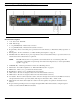
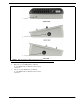
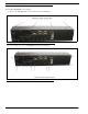
Rear Panel Descriptions
1. AC Power Connector
2. DB-9 (female) Connector - Frame
3. RJ-45 Connector - Frame
4. RJ-45 Connector - Expansion
5. RJ-45 Connector - LCP (for future expansion)
6. Boot Loader Reset - For more information, see
“Download Firmware Using the BLR Function” on
page 42.
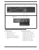
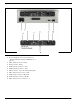
Optional GPI 32 CLD Module
7. DB-15 Connector - Aux 3 through Aux 6
8. DB-9 (male) Connector - Relay 1, 2, 3
9. DB-9 (male) Connector - Opto 1-4 IN
10. DB-9 (male) Connector - OC 1 and 2 OUT
11. DB-9 (male) Connector - Headset
12. DB-9 (male) Connector - Footswitch/Speaker
13. XLR-3 (female) Connector - Aux 1
14. XLR-3 (female) Connector - Aux 2
15. XLR-3 (female) Connector - Mic IN
16. XLR-3 (male) Connector - Mic OUT
FIGURE 3. KP 32 CLD Back Panel and GPI 32 CLD Option Card