
CLD Color Keypanel Family User Manual


17
CHAPTER 2
Installation
KP 32 CLD Installation
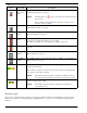
NOTE: You can use only one (1) type of Frame connection to the Matrix at a time.
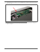
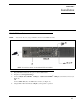
1. Plug the Power Cord (C) into the power connector KP 32 CLD.
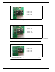
2. If required, set the keypanel address.
3. Connect an RJ11 cable with RTS
®
cabling (E) or RJ45 cable with RTS
®
cabling (F) to the frame connector (see
Figure 13).
OR
Connect a DB9 cable (G) to the DB9 frame connector (see Figure 13).
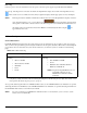
4. Using the KP 32 CLD and AZedit, configure your keypanel for operation.
FIGURE 13. KP 32 CLD Installation