
CLD Color Keypanel Family User Manual


19
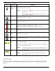
Connections
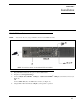
Frame Connector
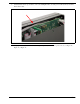
Use either of the Frame connectors (but not both) to connect to an intercom port of the intercom system. For frame connector
locations, see Figure 3 on page 7. The intercom port you connect to should agree with the address you set previously.
Headset Connector
A stereo headset may be connected to the front of the unit (or rear, with optional GPI 32 CLD option card installed) for use
along with or in place of the front/rear panel speaker and a separate microphone. Headphones may be connected for use with a
separate microphone.
Panel Microphone Connector
A panel microphone may be connected to the front (or rear, with optional GPI 32 CLD option card installed) of the unit for
talking with either the front/rear panel speaker or headphones used for listening. The connector accepts MCP5, MCP6, or
MCP90 series panel microphones. Insert the microphone and rotate the entire microphone body several turns to lock in place.
Footswitch Connector
A 6- or 7-pin headset connector may replace the standard 4- or 5-pin headset connector to include a front footswitch to the
front panel of the KP 32 CLD, in place of the headset connector.