RTS Automatic Transfer Switch 400A, 120/240V, Single-phase Model No.: KGATX0101400 TECHNICAL MANUAL A new standard of reliability This manual should remain with the unit.
Important Safety Instructions Also read the instructions and information on tags, decals, and labels that may equipment. be affixed to the transfer switch. Replace any decal or label that is no longer legible.
Table of Contents • Because jewelry conducts electricity, wearing it may cause dangerous electrical shock. Remove all jewelry (such as rings, watches, bracelets, etc.) before working on this equipment. • If work must be done on this equipment while standing on metal or concrete, place insulative mats over a dry wood platform. Work on this equipment only while standing on such insulative mats. • Never work on this equipment while physically or mentally fatigued.
Section 1 — General Information RTS “W” Type Transfer Switch 1.1 INTRODUCTION This manual has been prepared especially for the purpose of familiarizing personnel with the design, application, installation, operation and servicing of the applicable equipment. Read the manual carefully and comply with all instructions. This will help to prevent accidents or damage to equipment that might otherwise be caused by carelessness, incorrect application, or improper procedures.
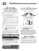
Section 2 — Installation RTS “W” Type Transfer Switch 2.1 INTRODUCTION TO INSTALLATION This equipment has been wired and tested at the factory. Installing the switch includes the following procedures: • Mounting the enclosure. • Connecting utility and generator power source leads. • Connecting the load leads. • Connecting any auxiliary contact (if needed) • Installing/connecting any options and accessories. • Testing functions. 2.2 2.4.1 2-POLE MECHANISM These switches (Figure 2.
Section 3 — Operation RTS “W” Type Transfer Switch NOTE: Use a torque wrench to tighten the conductors, being sure not to overtighten, or damage to the switch base could occur. If undertightened, a loose connection would result, causing excess heat which could damage the switch base. Connect power source load conductors to clearly marked transfer mechanism terminal lugs as follows Auxiliary Contacts are rated 10 amps at 125 or 250 volts AC. DO NOT EXCEED THE RATED VOLTAGE AND CURRENT OF THE CONTACTS.
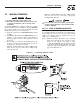
Section 3 — Operation RTS “W” Type Transfer Switch 3.2 MANUAL OPERATION DANGER NOT manually transfer under load. Do Disconnect transfer switch from all power sources by approved means, such as a main circuit breaker(s). A manual HANDLE is shipped with the transfer switch. Manual operation must be checked BEFORE the transfer switch is operated electrically. To check manual operation, proceed as follows: 1. Turn the generator’s AUTO/OFF/MANUAL switch to OFF. 2.
Section 3 — Operation RTS “W” Type Transfer Switch 3.2.2 CLOSE TO EMERGENCY SOURCE SIDE 3.3.2 GENERATOR VOLTAGE CHECKS Before proceeding, verify the position of the switch by observing window “B” in Figure 3.1. If window “B” reads “ON”, the contacts are closed in the EMERGENCY (STANDBY) position. No further action is required. If it reads “OFF”, proceed with Step 1. 1. On the generator panel, set the AUTO/OFF/ MANUAL switch to MANUAL position. The generator should crank and start. 2.
Section 3 — Operation RTS “W” Type Transfer Switch 3.4 GENERATOR TESTS UNDER LOAD 1. Set the generator's main circuit breaker to its OFF or OPEN position. 2. Manually actuate the transfer switch main contacts to their EMERGENCY (STANDBY) position. Refer to “Manual Operation” section. 3. To start the generator, set the AUTO/OFF/MANUAL switch to MANUAL. When engine starts, let it stabilize for a few minutes. 4. Turn the generator's main circuit breaker to the ON or CLOSED position.
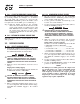
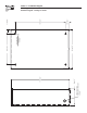
8 TRIPLE EKO SUITABLE FOR 1", 1.25" & 1.50" CONDUIT 3 PLACES 254mm[10.0"] 917mm[36.1"] 609.6mm[24.0"] 487mm[19.2"] MOUNTING HOLES: Ø6.35mm[Ø0.25"] 4-PLACES 60.8mm[2.4"] 794mm[31.3"] 61.3mm[2.4"] Section 4 — Installation Diagram RTS “W” Type Transfer Switch Installation Diagram – Drawing No.
Section 5 — Electrical Data RTS “W” Type Transfer Switch Interconnection Diagram - Drawing No.
Section 5 — Electrical Data RTS “W” Type Transfer Switch Wiring Diagram/Schematic – Drawing No.
Section 5 — Electrical Data RTS “W” Type Transfer Switch Wiring Diagram/Schematic – Drawing No.
Section 6 — Exploded Views and Parts List RTS “W” Type Transfer Switch 400 A Switch Assembly – Drawing No.
Section 6 — Exploded Views and Parts List RTS “W” Type Transfer Switch 400 A Switch Assembly – Drawing No. 0G1510$ ITEM PART NO.
Section 8 — Warranty RTS “W” Type Transfer Switch CARRIER WARRANTY/SERVICE Carrier will warrant that from the date of purchase, our transfer switch will be free from defects in material and workmanship for the items and periods set forth in the warranty statement found in the owners manual of the Carrier generator that this transfer switch will be utilized with. Any equipment that the purchaser/owner claims to be defective must be examined by the nearest Carrier Dealer.