ADAMTM CS Advanced Digital Audio Matrix SYSTEM INSTALLATION GUIDE ADAM CS TM Advanced Digital Audio Matrix POWER GOOD ™ 9330-7517-000 Rev G3 10/97 POWER GOOD
PROPRIETARY NOTICE CUSTOMER SUPPORT The RTS product information and design disclosed herein were originated by and are the property of Telex Communications, Inc. Telex reserves all patent, proprietary design, manufacturing, reproduction, use and sales rights thereto, and to any article disclosed therein, except to the extent rights are expressly granted to others. Technical questions should be directed to: Customer Service Department RTS/Telex, 2550 Hollywood Way, Suite 207 Burbank, CA 91505 U.S.A.
TABLE OF CONTENTS ADAM CS Front Panel Description · · · · · · · · · · · · · · · · · · · · · · · · · · · · · · · · · · · · · · · · · · · · · · · · · · · · · · · · · · · · · · · · · · · 7 ADAM CS Back Panel Description · · · · · · · · · · · · · · · · · · · · · · · · · · · · · · · · · · · · · · · · · · · · · · · · · · · · · · · · · · · · · · · · · · · 7 ADAM CS Frame Installation· · · · · · · · · · · · · · · · · · · · · · · · · · · · · · · · · · · · · · · · · · · · · · · · · · · · · · · · · · · · · · · · · · ·
General Description · · · · · · · · · · · · · · · · · · · · · · · · · · · · · · · · · · · · · · · · · · · · · · · · · · 13 General Theory of Operation · · · · · · · · · · · · · · · · · · · · · · · · · · · · · · · · · · · · · · · · · · · · · 13 Trunking Connections and Setup · · · · · · · · · · · · · · · · · · · · · · · · · · · · · · · · · · · · · · · · · · · 13 Program Assign Panel Installation · · · · · · · · · · · · · · · · · · · · · · · · · · · · · · · · · · · · · · · · · · · · · · · · · · · · · · · · ·
LIST OF FIGURES Figure 1. ADAM CS Front View · · · · · · · · · · · · · · · · · · · · · · · · · · · · · · · · · · · · · · · · · · · · · · · · · · · · · · · · · · · · · · · · · · · · 18 Figure 2. ADAM CS Back View (Shown with RJ-11 Connector Panel) · · · · · · · · · · · · · · · · · · · · · · · · · · · · · · · · · · · · · · 18 Figure 3. ADAM CS J900 to Computer Interconnect Cables (ADAM CS with male J900 Connector) · · · · · · · · · · · · · · 19 Figure 4.
LIST OF TABLES Table 1. ADAM CS Master Controller Card DIP Switch Settings (S1) · · · · · · · · · · · · · · · · · · · · · · · · · · · · · · · · · · · · · · · 30 Table 2. Relationship between Audio Input/Output Cards, Intercom Ports, and Logical Keypanel Numbers· · · · · · · · · · 31 Table 3. Address DIP Switch Settings for KP-95/96/97/98 Keypanels and the TIF-951 Telephone Interface · · · · · · · · · 31 Table 4.
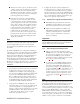
NOTICE: These servicing instructions are for use by qualified personnel only. To avoid electric shock do not perform any servicing other than that contained in the Operating Instructions unless you are qualified to do so. 1 ADAM CS Front Panel Description (Figure 1, page 18) There are 10 card slots in the front panel. Starting from the left side, slots 1 through 8 are for Audio Input/Output Cards. Slots 9 and 10 are for main and backup Master Controller Cards.
4.2 Unused Card Slots To ensure proper air flow, each unused front card slot should be fitted with a card blank (part number 9000-7467-003) to cover the opening. 4.3 Card Reset and Fail Indication Each circuit card is equipped with a reset switch located near the top-front of the card. Directly under the reset switch is a red fail indicator. The fail indicator remains off during normal operation.
supply, and repair or replace it as soon as possible to assure continued backup protection in the event of another power supply failure. other types of audio devices could also be connected. For example, a program source could be connected to the audio input wires, and in this case the audio output wires would not be used. Note The power supply alarm will also sound if a power supply is not turned on. This is normal. Either turn on the power supply, or set the ALARM OVERRIDE switch.
Write down a name of up to four characters in the "Alpha" column of the worksheet. You will enter this name into the intercom system later using ADAMedit or CSedit. Then, whenever you assign the port to an intercom key, the name will appear in the keypanel display for that key.
expansion panels. For further information, see "SERVICE MENU, MOD ASGN" in the KP-12 Operating Instructions Manual Plug in the AC power cords for the KP-12 and any other connected panels. (Or, the external DC power supplies where used.) When the KP-12 is connected and turned on for the first time, the call waiting window will display "SET ADDR". This means you have to set the logical keypanel address.
4. For each intercom port used by the TIF-951, set the Logical Keypanel Number DIP switches on the back of the TIF-951 as summarized in Table 3, page 31. (Refer to the Planning Worksheet if you are unsure what is the correct Logical Keypanel Number.) For all other TIF-951 DIP switch settings, refer to the TIF-951 User Manual. Important! Do not use the address DIP switch settings as shown in the TIF-951 User Manual, as those address settings are only appropriate for a CS9000 Series Intercom System. 11.
key to get help. Then, within ADAMedit help, click the Search button, type the keyword “keypanel”, and press Enter. Finally, choose “Keypanel Setup” from the resulting list. talk or listen just like in their own intercom system. There is no apparent difference to keypanel operators, but what actually occurs in the system electronics is slightly different. For each intercom port, the PL1 through PL4 keys on the CDP-950 correspond to keys 12 through 15 in the CSedit or ADAMedit key assignment table.
get by with fewer trunk lines than the number of potential users. For example, if two keypanels need to have access to another intercom system, but only one of those keypanels has a critical need, you may be able to get by with one trunk line. You can just set the trunk priorities for the two users (as described in the following paragraphs) so that the one with the critical need has a higher priority.
remember to enter the alias name if this is different from the alpha name. Press the F1 key on the computer keyboard to get help on keypanel setup. 7. This completes the general procedure to setup and use trunking. Remember to save any changes that you make in CSedit, CStrunk, or ADAMedit, and send your changes to the intercom system and/or the trunking system in order for them to take effect. 13 Program Assign Panel Installation 13.
control a different range of program inputs, it will be necessary to reprogram the EEPROM in all but one panel. (Contact your intercom system dealer for assistance.) Finally, it is possible to define which range of IFB's are controlled by each Program Assign Panel as described below.
that each frame controls a unique range of GPI inputs and GPI outputs. 3. GPI inputs are connected via a 50-pin telco connector on the back of the UIO-256. Each input requires +18 VDC for activation. The +18 VDC and common connections may be provided from a remote source. Or, 18 VDC is supplied at the connector by the UIO-256 and may be used for input activation, with the user supplying the external switch. 15.4 A second 50-pin telco connector is provided for relay output connections.
ADAM CS ™ Advanced Digital Audio Matrix Card Reset Switch Card Fail Indicator +2.1V +2.1V +5V +5V +15V +15V -15V -15V POWER GOOD POWER GOOD PS1 PS2 Power Supply #2 Power Supply #1 Backup Controller Card Main Controller Card Audio I/O Card #8 Audio I/O Card #7 Audio I/O Card #6 Audio I/O Card #5 Audio I/O Card #4 Audio I/O Card #3 Audio I/O Card #2 Audio I/O Card #1 ALARM OVERRIDE AC1 Connector for PS1 Power Supply AC2 Connector for PS2 Power Supply Figure 1.
TO INTERCOM SYSTEM 9-PIN TO 25-PIN CABLE TO COMPUTER RX 2 2 TX TX 3 3 RX GND 5 7 GND 25-PIN FEMALE CONNECTOR (DB-25S) 9-PIN FEMALE CONNECTOR (DE-9S) TO INTERCOM SYSTEM 9-PIN TO 9-PIN CABLE TO COMPUTER RX 2 2 RX TX 3 3 TX GND 5 5 GND 9-PIN FEMALE CONNECTOR (DE-9S) 9-PIN FEMALE CONNECTOR (DE-9S) Figure 3.
CONTACTS RJ 11 MOD PLUG AMP 55550423 or equivalent (View from cable entrance) 123456 Use AMP Crimp Tool 12316661 DE-9P (MALE) RJ11 LATCH DATA - 1 DATA - 1 AUDIO FROM MATRIX + 2 AUDIO TO MATRIX + 3 4 DATA + 6 5 AUDIO FROM MATRIX - 5 7 DATA + 6 1 2 Figure 8. RJ-11 to 9-Pin Intercom Cable. Use for TIF-951 Connection to ADAM CS with RJ-11 Back Panel.
KP-12 OPTIONAL SECOND EKP (MUST RESET MOD NUMBERS) EKP J1 EXP J2 DC J2 DC OPTIONAL SECOND LCP (MUST RESET MOD NUMBERS) LCP J1 J1 J2 DC J1 ALL INTERCONNECTIONS BETWEEN PANELS USE SUPPLIED RJ-45 CABLES J2 DC TO J1 OF A THIRD EKP (OPTIONAL) Figure 10. Typical connections of EKP's and LCP's to a KP-12 DE-9S (Female) DE-9P (Male) 6 7 1 2 2 1 TO ADAM CS, J902 TO: PAP-940, PAP-951, OR PAP-952 Figure 11.
DE-9S (Female) DE-9P (Male) 9 6 5 1 4 2 Figure 13. Single-Pair Data Cable DA-15P (Male) DA-15P (Male) 1 2 3 4 5 9 10 11 12 13 14 15 1 2 3 4 5 9 10 11 12 13 14 15 Figure 15. 15-Pin Data Cable 12 VDC DE-9S (Female) DE-9P (Male) 6 1 1 2 GPI OUT + 22 K 2 TO ADAM CS, J902 TO: UIO-256, J2 10 K DE-9P (Male) GPI OUT - 7 2 1 Figure 16.
DE-9S (FEMALE) 1 2 6 1 DE-9S (Female) DE-9P (Male) 2 3 6 1 4 1 2 5 2 TO ADAM CS, J902 6 TO UIO-256, J2 Figure 22. UIO-256 to ADAM CS Interconnect Cable 1 1 2 2 3 3 4 4 5 5 6 6 RJ 11 MOD PLUG DE-9P (MALE) RJ 11 MOD PLUG DE-9S (FEMALE) 1 2 6 1 2 6 8 7 3 + - 8 7 3 1 2 3 4 5 6 7 8 9 DE-9P (MALE) 1 2 3 4 5 6 7 8 9 Figure 21. ICP-97-TMX to SWP-71-T Interconnect Cable DE-9S (FEMALE) + - + - 4 5 9 Figure 20.
DE-9S (FEMALE) TO AN INTERCOM PORT + - 1 2 7 TO CDP-950 2 6 TO AN INTERCOM PORT 1 1 2 6 TO AN INTERCOM PORT 4 5 9 7 8 3 + - 1 2 3 4 5 6 SINGLE PAIR DATA CABLE FOR CONNECTION OF CDP-950 ONLY DE-9S (FEMALE) DE-9P (MALE) RJ 11 MOD PLUG DE-9P (MALE) 7 2 TO CDP-950 1 SINGLE PAIR DATA CABLE FOR CONNECTION OF CDP-950 ONLY DE-9P (MALE) DATA + - 1 2 6 AUDIO TO MATRIX + - 4 5 TO INTERCOM STATION TO AN INTERCOM PORT 1 1 2 2 3 3 4 4 5 5 6 6 9 AUDIO FROM MATRIX RJ 11 MOD PLUG
Figure 24.
To AC1 To AC2 J1 J2 FR9589 MASTER CONTROLLER A (MAIN) J6 J7 J8 J3 J4 J5 SHORTING PLUG (MAIN ONLY) DE9P NOTE 1 1 NOTE 1 6 J1 J3 ICP-97-TMX #1 J6 J7 J8 J9 J10 J11 J12 #1 #2 #3 #4 #5 J5 NOTE 2 INTERCOM SYSTEMS (NOTE 4) #6 #7 J1 #8 J3 ICP-97-TMX #2 J5 J6 J7 J8 J9 J10 J11 J12 TO PC NOTE 3 Figure 25. Trunking System Connections for up to Eight Intercom Systems, without Backup Controller Notes: 1. 50-pin telco cable. See Figure 24. 2. Single pair data cable. See Figure 13.
To AC1 To AC2 J1 J1 J2 J7 J8 J3 J4 J2 FR9589 MASTER CONTROLLER B (BACKUP) FR9589 MASTER CONTROLLER A (MAIN) J6 To AC2 To AC1 J6 J5 SHORTING PLUG (MAIN ONLY) DE9P J7 J8 J3 J4 J1 J3 J5 NOTE 1 NOTE 1 1 NOTE 1 6 J1 J3 ICP-97-TMX #1 J5 J6 J7 J8 J9 J10 J11 J12 NOTE 1 NOTE 2 INTERCOM SYSTEMS (NOTE 4) #1 #2 #3 #4 #5 #6 #7 J1 #8 J3 ICP-97-TMX #2 J5 J6 J7 J8 ICP-97-TMX #3 J9 J10 J11 J12 J5 J6 J7 J9 J10 J11 J12 J8 NOTE 5 NOTE 5 NOTE 3 J1 J2 J3 J4 J5 J6
To AC1 To AC2 J1 J2 FR9589 MASTER CONTROLLER A (MAIN) J6 J7 J8 J3 J4 J5 NOTE 1 SHORTING PLUG NOTE 1 DE9P 1 NOTE 1 6 J1 J3 J1 ICP-97-TMX #1 ICP-97-TMX #2 J6 J7 J8 J9 J10 J11 J12 TO INTERCOM #1 #2 SYSTEMS (NOTE 4) #3 #4 #5 J5 J3 J5 J6 J7 J8 J9 J10 J11 J12 NOTE 2 #6 #7 #8 . . . . . . #9 #10 #11 #12 J1 J3 ICP-97-TMX #3 J5 J6 J7 J8 J9 J10 J11 J12 NOTE 3 TO PC Figure 27.
To AC1 To AC2 J1 J7 J8 J3 J4 J2 J1 J2 FR9589 MASTER CONTROLLER B (BACKUP) FR9589 MASTER CONTROLLER A (MAIN) J6 To AC2 To AC1 J6 J5 NOTE 1 J7 J8 J3 J5 J4 NOTE 1 SHORTING PLUG (MAIN ONLY) DE9P NOTE 1 1 NOTE 1 6 J1 J3 J1 ICP-97-TMX #1 J5 J6 J7 J8 J3 ICP-97-TMX #2 J9 J10 J11 J12 J5 J6 J7 J8 J9 J10 J11 J12 NOTE 2 #1 #2 #3 #4 TO INTERCOM SYSTEMS (NOTE 4) #5 #6 #7 #8 . . . . . .
Table 1. ADAM CS Master Controller Card DIP Switch Settings (S1) Switch No. Description On=closed; Off=open Default Setting1 On=closed; Off=open 1 CSedit / ADAMedit baud rate select2 Off: 9600 baud On: 38.4 Kbaud Off 2 Keypanel Incoming message option3 Off: Normal operation On: All callers display in Incoming Messages window Off 3 Keypanel "in-use" and "busy" flash4 Off: Enable On: Disable Off 4 Trunk master baud rate select.5 Off: 38.
Table 2. Relationship between Audio Input/Output Cards, Intercom Ports, and Logical Keypanel Numbers Card 1 Card 2 Card 3 Card 4 Card 5 Card 6 Card 7 Card 8 ADAM CS Intercom Port Numbers (Grouped by Audio Input/Output Card Number) Logical Keypanel Number (See Table 3 for DIP switch settings.
Table 6. Program Assign Panel DIP Switch Setting for IFB Range Table 4.
Table 8. UIO-256 DIP Switch SW1 Settings for Input/Output Range UIO-256 Frame Input/Output Range #1 DIP Switch Settings 1 2 3 4 5 6 7 8 1-16 Open Open Open Open Open Open Open Closed #2 17-32 Open Open Open Closed Open Open Open Closed #3 33-48 Open Open Open Open Closed Open Open Closed #4 49-64 Open Open Open Closed Closed Open Open Closed Table 9.
Table 10.
Table 11. Planning Worksheet for ADAM CS with RJ-11 or DE9 Back Panel, Sheet 1 of 3 ADAM CS Connector No. ADAM CS Audio I/O Card No. Logical Keypanel Number* Port No.
Planning Worksheet for ADAM CS with RJ-11 or DE9 Back Panel, Sheet 2 of 3 ADAM CS Connector No. ADAM CS Audio I/O Card No. Logical Keypanel Number* Port No.
Planning Worksheet for ADAM CS with RJ-11 or DE9 Back Panel, Sheet 3 of 3 ADAM CS Connector No. ADAM CS Audio I/O Card No. Logical Keypanel Number* Port No.
Table 12. Planning Worksheet for ADAM CS with 50-Pin Telco Back Panel, Sheet 1 of 3 38 ADAM CS Installation Manual ADAM CS Audio Input/Output Card No. Audio Input Connector Audio Output Connector Data Connector (+) Pin (-) Pin Logical Keypanel Number* Port No.
Planning Worksheet for ADAM CS with 50-Pin Telco Back Panel, Sheet 2 of 3 ADAM CS Installation Manual 39 ADAM CS Audio Input/Output Card No. Audio Input Connector Audio Output Connector Data Connector (+) Pin (-) Pin Logical Keypanel Number* Port No.
ADAM CS Installation Manual Planning Worksheet for ADAM CS with 50-Pin Telco Back Panel, Sheet 3 of 3 ADAM CS Audio Input/Output Card No. Audio Input Connector Audio Output Connector Data Connector (+) Pin (-) Pin Logical Keypanel Number* Port No.
INDEX A Customer Support 2 Audio I/O Card F Card Slot Numbers 7 Front Panel Front panel view 18 Description 7 System clock signals 8 Front View 18 B G Back Panel General Purpose I/O Connector (J903) Back View 18 Connector pin-out 32 Description 7 Description and Connections 16 C Programming Digital Inputs 16 CDP-950 Programming Digital Outputs 16 Cable Wiring Diagrams 24 I Installation Notes 12 Intercom Port Range select DIP switch settings 32 9-Pin D-sub intercom cable wiring diagram 20 Circuit Card Genera
U Description 15 UIO-256 DIP switch settings for IFB range 32 DIP switch settings for panel number selection 32 15-pin data cable wiring to interconnect multiple UIO-256's 22 Setup and Connections 15 ADAM CS interconnect cable wiring diagram 23 Description and Connections 16 Planning Worksheets ADAM CS with 50-pin telco back panel 38 DIP switch settings for I/O range selection 33 ADAM CS with RJ-11 or DE9 back panel 35 GPI outputs connector pin-out 33 Opto-isolator inputs connector pin-out 34 Power