
Service manual


3.1.1 J201 (EXTERNAL INPUT MUTING)
When pins 2 and 3 are shorted, a signal input at the EXT
LINE IN connector is muted when any Talk key is
pressed. When pins 1 and 2 are shorted, the signal is not
muted during Talk key activation.
3.1.2 J202 (SPEAKER/HDST MUTE)
When pins 1 and 2 are shorted, the speaker/headset signal
is fully muted when any Talk keys are pressed. When pins
2 and 3 are shorted, the signal is muted by 15 dB when
any Talk keys are pressed.
3.1.3 J203 (SIDETONE MUTING)
When pins 1 and 2 are shorted, the sidetone signal is al-
ways on. When pins 2 and 3 are shorted, the sidetone sig-
nal is on only when a Talk key is pressed.
3.1.4 J401 (OUTPUT ENABLE)
When the jumper is installed, the microphone is on only
when any Talk key is pressed. When the jumper is re-
moved, the microphone will always be on.
3.1.5 J402 (BALANCE TEST)
For normal operation, there should be no jumper installed.
This jumper is used when adjusting the keypanel audio
levels. See “Balance Adjustment”, page
15.
3.1.6 J403 (PREAMP OUT)
When pins 1 and 2 are shorted, the mic signal at the MIC
PRE OUT connector is switched on and off by the Talk
keys. When pins 2 and 3 are shorted, the mic signal at the
MIC PRE OUT connector is always on.
3.1.7 J404-J406 (PANEL MIC SELECTION)
These jumpers work together to configure the panel mi-
crophone preamp for various types of microphones as fol-
lows:
2-Wire Electret:
J404 Pins 1 and 2 shorted
J405 No jumper
J406 No jumper
3-Wire Electret:
J404 No jumper
J405 No jumper
J406 No jumper
Balanced Dynamic (-70 dB, 150 ohms):
J404 Pins 2 and 3 shorted
J405 Pins 1 and 2 shorted
J406 Pins 1 and 2 shorted
3.2 AUDIO LEVEL ADJUSTMENTS
3.2.1 GENERAL
The following paragraphs describe the procedures to cali-
brate the output level to the factory standard of +8 dBu. If
a different level is required, substitute that level for +8
dBu.
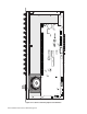
Most audio level trimmers are accessible through access
holes on the back of the keypanel. Each trimmer access
hole is labeled with its function. Some trimmers are inter-
nal, and can only be accessed with the top cover removed.
Locations of trimmers are shown in Figure .
7
Audio levels may be adjusted with the panel disconnected
from the intercom system. However, proper operation
should be confirmed when the panel is reconnected. If
levels change after reconnection, check the intercom sys-
tem wiring for one-sided shorts to ground, wiring errors,
or unintended terminations.
Connector pin-outs for these connectors were presented
earlier in this section. If the keypanel under adjustment
does not have these connectors, refer to drawing number
IKP-950/2-5 (in the Keypanel Drawings and Parts Man-
ual). The IKP-950/2-5 drawing shows equivalent locations
where test equipment may be connected.
Required test equipment:
Audio Signal Generator with balanced output
Audio Signal Analyzer with balanced input
DC Millivoltmeter
Oscilloscope - any commercially available type
3.2.2 MICROPHONE PREAMPLIFIER
1. Set the HDST switch to off.
2. Remove the gooseneck microphone, and insert a -70
dBm signal (1KHz at 150 ohms) into the microphone
connector. Or use the EXT MIC IN connector with
the front panel microphone removed (ref Table
7,
page 12 for pin-out).
3. Activate the microphone by setting a Talk key to the
latched-up position.
Installation Instructions, KP95-0 Keypanel 13