BTR-80N, TR-80N, TR-82N Professional Wireless Intercom System Operating Instructions F.01U.195.915 Rev.
BTR-80N, TR-80N, TR-82N PROPRIETARY NOTICE The product information and design disclosed herein were originated by and are the property of Bosch Security Systems, Inc. Bosch reserves all patent, proprietary design, manufacturing, reproduction, use and sales rights thereto, and to any article disclosed therein, except to the extent rights are expressly granted to others. COPYRIGHT NOTICE Copyright 2019 by Bosch Security Systems, Inc. All rights reserved.
BTR-80N, TR-80N, TR-82N 3 Important Safety Instructions 1. Read these instructions. 2. Keep these instructions. 3. Heed all warnings. 4. Follow all instructions. 5. Do not use this apparatus near water. 6. Clean only with dry cloth. 7. Do not block any ventilation openings. Install in accordance with the manufacturer’s instructions. 8. Do not install near any heat sources such as radiators, heat registers, stoves, or other apparatus (including amplifiers) that produce heat. 9.
BTR-80N, TR-80N, TR-82N
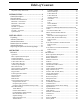
Table of Contents OPERATION ..................................................25 CAN Bus Number ................................................36 Intercom Settings ..................................................36 2-Wire Intercom ...................................................37 4-Wire Intercom ...................................................37 Auxiliary Settings .................................................38 ClearScan .............................................................
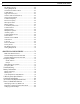
BTR-80N, TR-80N, TR-82N RF Monitor Screen .................................................. 62 Setting Beltpack ID ................................................. 62 On/Off and Volume Control ................................... 63 TALK Button .......................................................... 63 Stage Announce (SA) ............................................. 63 Wireless Talk-Around (WTA) ................................ 64 Groups and Channels .............................................
CHAPTER 1 Introduction General Description System Features RTS Wireless BTR-80N UHF Synthesized Wireless Intercom system offers reliable, high-performance, high-fidelity fullduplex communications delivered with minimum spectrum usage. • Frequency-agile base station and beltpacks. No external computer/device required to select frequencies. • Backlit base-station LCD allows the user to easily monitor the beltpack’s status and change base station frequencies.
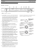
10 Introduction BTR-80N, TR-80N, TR-82N Controls and Connections BTR-80N – Front Panel FIGURE 1. BTR-80N - Front Panel 1. Power Switch - Do not power up a base station within three (3) seconds of the unit being turned off. Voltages within the unit need to drop below a threshold before being repowered. If powered-up in less than three (3) seconds, the unit may boot as the wrong frequency band. Even with the unit powered down via the power switch, some circuits within the base remain energized.
BTR-80N, TR-80N, TR-82N BTR-80N – Rear Panel FIGURE 3. BTR-80N - Rear Panel 1. Receive Antenna - Female “TNC” Connector. Color band on antenna must match color dot on base station. 2. Relay Contact - A dry contact closure which activates when a beltpack user presses the stage announce (SA) button. Normally Open (NO). The rating is one amp at 24V maximum. 3. Program Connector - Used to update software in unit. 4.
12 Introduction BTR-80N, TR-80N, TR-82N Specifications Overall RF Frequency TX Range 482 - 608 MHz in 18 MHz TX bands RX Range US/Canada 572 - 608 MHz in 18 MHz RX bands 653 - 663 MHz for 3 band Rest of the World 572 - 608, 614 - 722 MHz in 18 MHz RX bands Power Requirements 100 - 240 VAC, 50 - 60 Hz 1 Amp Max,, IEC receptacle DC Only 12 - 15 VDC, 3.5 Amps Temperature Range -4° F to 130° F (-20° C to 55° C) Dimensions 19.00” W x 1.72” H x 14.00” D (48.3cm x 4.4cm x 35.6cm) Weight 7lbs 2oz (3.
BTR-80N, TR-80N, TR-82N Stage Announce Relay Dry contact, rated at 1 Amp, 24V Max Microphone Input Sensitivity 9mV Local Headset Output 40mW output into 600Ω (1% Distortion) Transmitter Type Two Synthesized Transmitters Transmit Power (each transmitter) Selectable: off, 10mW, 50mW, 100mW, 249mW Modulation Type FM Deviation 4kHz RF Frequency Stability 2.
14 Introduction BTR-80N, TR-80N, TR-82N TR-80N - Top Panel FIGURE 4. TR-80N Top Panel 1. On/Off Volume Control - Turns the beltpack power on. 2. Wireless Talk-Around (WTA) - When pressed, the user’s audio disconnects from the wired intercom, auxiliary input/ output and the base station’s local headset. Other beltpack users on the audio channel can hear the user as normal. The button activates the nearby red LED and the TALK button. 3.
BTR-80N, TR-80N, TR-82N Introduction 15 . FIGURE 5. TR-80N Rear Panel/Connector/Antennas 1. MENU and SET buttons- Use to select menus and set options on the LCD. 2. LCD (Liquid Crystal Display) 3. UP and DOWN buttons - Use to select beltpack options on the LCD. 4. Programming Connector - Use to update software in unit. 5. Headset Connector - Male XLR or female XLR connector.
16 Introduction BTR-80N, TR-80N, TR-82N Specifications Overall RF Frequency TX Range US/Canada 572 - 608 MHz in 18 MHz TX bands 653 - 663 MHz for 3 band Rest of the World 572 - 608, 614 - 722 MHz in 18 MHz TX bands RX Range 482 - 608 MHz in 18 MHz RX bands Power Requirements 6 “AA” Cells Alkaline (NiHM Optional) Current Draw 200mA (Push-To-Talk, Talk On) Temperature Range -4°F to 130°F (-20°C to 55°C) Dimensions 3.75” W x 5.05” H x 1.65” D (9.5cm x 12.8cm x 4.
BTR-80N, TR-80N, TR-82N RF Frequency Stability 2.5PPM Modulation Limiter Peak-Responding Compressor Radiated Harmonics &Spurious Exceeds FCC specifications Receiver Type Triple Conversion Superheterodyne, Synthesized FM RF Sensitivity <0.6V for 12dB SINAD Squelch Threshold adjustable - 12/20/24dB SINAD (about 1.0 μV) IF Selectivity 6dB at 30kHz bandwidth Image Rejection 70dB or better Squelch Quieting 90dB RF Frequency Stability 2.
18 Introduction BTR-80N, TR-80N, TR-82N TR-82N – Top Panel FIGURE 7. TR-82N Top Panel 1. On/Off and Volume Control - Turns beltpack power on and controls headset volume for intercom channels “1” and “2”. Either knob, “1” or “2”, turns the beltpack on. Both knobs must be off to turn the beltpack off. If only one knob is on, the intercom channel “1” or “2” is on for both transmit and receive. 2.
BTR-80N, TR-80N, TR-82N FIGURE 8. TR-82N Rear Panel/ Connector/Antennas 1. MENU and SET buttons - Used to select menus and set options on the LCD. 2. LCD (Liquid Crystal Display) 3. UP and DOWN buttons - Used to select beltpack options on the LCD. 4. Programming Connector - Used to update software in unit. 5. Auxiliary Input Audio Jack - 1/85” (3.5mm) mono input jack. Local only to beltpack. 6. Introduction 19 Headset Connector - Male XLR connector or female XLR.
20 Introduction BTR-80N, TR-80N, TR-82N Specifications Overall RF Frequency TX Range US/Canada 572 - 608 MHz in 18 MHz TX bands 653 - 663 MHz for 3 band Rest of the World 572 - 608, 614 - 722 MHz in 18 MHz TX bands RX Range 482 - 608 MHz in 18 MHz RX bands Power Requirements 6 “AA” Cells Alkaline (NiHM Optional) Temperature Range -4° F to 130° F (-20° C to 55° C) Dimensions 3.75” W x 5.35” H x 2.02” D (9.5cm x 13.5cm x 5.
BTR-80N, TR-80N, TR-82N Peak-Responding Compressor Radiated Harmonics &Spurious Exceeds FCC specifications Receiver Type Two, Triple Conversion Superheterodyne Receivers, Synthesized, FM RF Sensitivity <0.6 V for 12 dB SINAD Squelch Threshold adjustable - 12/20/24 dB SINAD IF Selectivity 6 dB at 30 kHz bandwidth Image Rejection 70 dB or better Squelch Quieting 90 dB RF Frequency Stability 2.
22 Introduction BTR-80N, TR-80N, TR-82N
CHAPTER 2 Installation Unpacking Unpack your RTS System. Below are the items that should come with your base station and each beltpack. Contact the shipper or your dealer immediately if anything is damaged or missing.
20 Installation BTR-80N, TR-80N, TR-82N Antenna Connection The base station is supplied with two (2) antennas. One 1/2wave antenna for transmit and one 1/2-wave for receive. The antennas have TNC male connectors. Attach the receive 1/2-wave antenna to the antenna input receptacle labeled Receive on the left side of the rear panel. The antenna should be vertically aligned. The frequency range of the antennas should match the receiver and transmitter of the base station.
BTR-80N, TR-80N, TR-82N Installation 21 Distance between Antennas The distance between the base station’s receive and transmit antennas is not adjustable when the antennas are connected directly on the back of the unit. The antennas can be remotely mounted for a better signal path. An RTS coax assembly with remote antennas may be required. See “Accessory” section for ordering information.
22 Installation BTR-80N, TR-80N, TR-82N Attempting to operate the wireless intercom system through or around walls, ceilings, metal objects, etc. reduces system range and performance. FIGURE 16. Operating System Near Obstructions IMPORTANT: DO NOT mount the base station 1/2wave antennas on or next to: metal, such as beams; walls with metal studs; or equipment racks, etc. This also applies to antennas assembled directly to the Base Station.
BTR-80N, TR-80N, TR-82N FIGURE 17. Installation 23 Antenna Placement Improving Reception and Increasing Range Keeping the distance from the base station and beltpack as short and unobstructed as possible produces the most reliable antenna performance. The base station is supplied with two (2) antennas. This provides satisfactory system performance in most applications. System range can be enhanced by remotely mounting the 1/2-wave antennas.
24 Installation BTR-80N, TR-80N, TR-82N
CHAPTER 3 Operation BTR-80N The base station also features: • A relay closure activated when the SA button is pressed at Operation This section discusses the operation and features of the BTR80N base station, opening with base operation and quick system setup. It then discusses basic interfacing and setup of a base station, then ends with the connection of multiple base stations and discussion of the links between them.
26 Operation BTR-80N, TR-80N, TR-82N FIGURE 18. BTR-80N Rear View Transmit and Receive Antennas The TNC transmit jack and receiver jack are both labeled on the rear of the unit. The base station comes with two (2) 1/2-wave antennas. Always match the color dot on the rear panel of the base station with the colored band on the antenna. The base station does not require wet intercom lines for operation. Wet intercom lines are those with D.C. voltages on them for powering 2-wire devices.
BTR-80N, TR-80N, TR-82N Loop-through of two base stations connected with Telex/Audiocom or Clear-Com Intercoms FIGURE 20. If multiple base stations are connected via 2 -wire intercom and no 2-wire power supply is involved to terminate the 2-wire, then termination plugs for the type of 2-wire system used must be at one end of each intercom line. Since RTS-TW carries both channels of audio on one (1) cable, the four (4) intercom XLR connectors are connected in parallel when RTS is selected.
28 Operation FIGURE 22. BTR-80N, TR-80N, TR-82N BTR-80N Rear View 4-Wire Intercom Ports The BTR-80N can connect to two (2) 4-wire audio intercom systems. These 6-pin modular jacks (RJ-11) are designated 4wire under intercom 1 and 2 titles on the rear panel. (See Figure 22). The jack’s pinout is shown in Figure 23. The auxiliary output jack is a 3-pin XLR jack. It produces a line level balanced output. Please refer to Figure 25. FIGURE 25.
BTR-80N, TR-80N, TR-82N FIGURE 26. Operation 29 BTR-80N Rear View Base Station Link Stage Announce (SA)/Relay This pair of RJ-45 jacks allow the passage of WTA, WTA termination control voltage, and CAN bus data between multiple base stations. Up to eight (8) base stations may be connected with the base station link. If just using WTA between bases, up to 16 base stations can be connected together.
30 Operation FIGURE 32. BTR-80N, TR-80N, TR-82N BTR-80N Base Station Link Jack and Program Jack Base Station Link Jack WTA 1 and WTA 2 in the BTR-80N are two (2) independent 2wire intercom channels. Up to 16 base stations may be connected together to share WTA audio. Do not confuse WTA audio with CAN bus data, as only eight (8) bases may be connected to share CAN bus data.
BTR-80N, TR-80N, TR-82N Operation 31 FIGURE 34. BTR-80N - Front Panel Powering the Base Station The base station may be powered two (2) different ways: • Line power at the IEC receptacle. Accepts 100–240VAC, 1A max., 50 or 60Hz. • 12–15VDC Power. Accepts a 5.5mm by 2.5mm screw on plug. Source must supply at least 3.5 Amps. To power on the base station, do the following: > Press the POWER button located on the far left of the base station front panel.
32 Operation BTR-80N, TR-80N, TR-82N RSSI Screen RSSI stands for Received Signal Strength Indicator. This screen displays the detected signal strength of each of the four (4) receivers in the base. User-defined groups 18u to 30u may be changed by the user to any frequency within range of the base. Group/Channel Screen To select the group and channel, do the following: FIGURE 37. 1. From the status screen, press MENU.
BTR-80N, TR-80N, TR-82N Operation 33 displays the group and frequencies selected, and then returns to the main screen. Frequency Edit (User-Defined Groups Only) The Frequency Edit screen is similar to the Group Frequency Select screen, but allows the complete editing of each transmit and receive frequency. FIGURE 41.
34 Operation BTR-80N, TR-80N, TR-82N Local Headset Volume and Gain To access the transmit power settings, do the following: The Local Headset Volume and Microphone Gain are set in the following software screen. 1. From the main status screen, press MENU. 2. Using the UP/DOWN arrow buttons, select Base Main. 3. Press SET. 4. Using the UP/DOWN arrow buttons, select TX-Power. 5. Press SET. The transmit power level starts flashing. 6. Using the UP/DOWN arrow buttons, adjust the level. 7.
BTR-80N, TR-80N, TR-82N Operation 35 5. Press SET. The receiver 1 squelch setting starts flashing. 6. Using the UP/DOWN arrow buttons, adjust the setting. 7. When finished, press SET. 8. Repeat steps six (6) and seven (7) to set the remaining receivers. 9. When finished, press SET. The Base Main selection menu appears. 10. Press MENU twice. The base menu select menu screen appears. NOTE: The base defaults back to the status screen if no action is taken after five (5) minutes.
36 Operation BTR-80N, TR-80N, TR-82N To enable or disable the antenna power, do the following: 1. From the status screen press MENU. 1. From the status screen, press MENU. 2. Using the UP/DOWN arrow buttons select More... 2. Using the UP/DOWN arrow buttons, select Base Main. 3. Press the DOWN arrow button. 3. Press SET. 4. Press SET until the Base Number option flashes. 4. Using the UP/DOWN arrow buttons, select MORE... . 5. Using the UP/DOWN arrow buttons, set the number. 5.
BTR-80N, TR-80N, TR-82N Operation 37 2-Wire Intercom 4-Wire Intercom The screens below show the progression of setting 2-wire parameters. The screens below show the progression of setting 4-wire parameters. FIGURE 49. 2-Wire Intercoms To adjust the 2-wire intercom settings, do the following: FIGURE 50. 4-Wire Intercoms To adjust the 4-wire intercom settings, do the following: 1. From the status screen, press the MENU button. 1. From the status screen, press the MENU button. 2.
38 Operation BTR-80N, TR-80N, TR-82N Auxiliary Settings The parameters to configure in the auxiliary setting menu are as follows: • Intercom 1 Auxiliary mode: Local, Global, or Off • Intercom 2 Auxiliary mode: Local, Global, or Off • Auxiliary input/output levels The auxiliary setting for Local, Global, and Off are defined as the following: Local Any audio placed into the auxiliary input port is routed only to the base’s local headset and beltpack(s).
BTR-80N, TR-80N, TR-82N Operation 39 Lockout 1st Use Defaults Lockout is used to keep a user from changing any options at the base station, except local headset microphone gain and volume. 1st Use Defaults is used to set the base station to Group 01A, channels 1, 2, 3, 4, and RETAIN any user-defined groups in memory. It sets the unit to factory-defined parameters. To enable Lockout, do the following: > Press and hold UP+DOWN for two (2) seconds to lock or unlock the base station.
40 Operation BTR-80N, TR-80N, TR-82N Connection of Multiple Base Stations with the Link Cables This section discusses various configurations of multiple base stations using link cables. Multiple base stations may be FIGURE 56. connected via standard 2-wire and 4-wire intercoms without additional link cables between them. They still transmit and receive intercom 1 and intercom 2 audio normally from the beltpacks.
BTR-80N, TR-80N, TR-82N Operation 41 Before presenting the configurations, we believe an explanation of RF data links plus master and servant base stations helps in understanding the multiple base arrangements. Over-the-Air Data Links There are two (2) RF data communication links within a BTR80N system. FIGURE 57.
42 Operation BTR-80N, TR-80N, TR-82N FIGURE 58.
BTR-80N, TR-80N, TR-82N Operation 43 Master and Servant Base Stations A master base station is one that the user has set its base number to 01(Master) and has its transmitters on. A master base conveys base-to-beltpack data to its beltpacks and via a base station link cable, relays the base-to-beltpack data from base stations that have their base transmitters off. A master may support up to seven (7) additional base stations with their transmitters off.
44 Operation BTR-80N, TR-80N, TR-82N CAN Bus 120 Ohm termination (CAN-T) and base pin functions. Part Number: PRD000223002 (not supplied) FIGURE 62. FIGURE 63.
BTR-80N, TR-80N, TR-82N Base Station Link Configurations Multiple base station networks may be connected in different ways. Using the rear panel base station link jacks, a user has three (3) different connection options.
46 Operation BTR-80N, TR-80N, TR-82N Wireless Talk-Around Audio Only These base stations are connected to share WTA channel 1 and WTA channel 2 audio but do not share the CAN bus data. If the WTA link cable passes from OUT to OUT or IN to IN, the WTA audio terminates in multiple places and causes the WTA audio levels to be greatly reduced/distorted. . Link Overview WTA 1 and WTA 2 in the BTR-80N are two (2) independent 2wire intercom channels.
BTR-80N, TR-80N, TR-82N Do not set base stations to the base number 01 (Master), because CAN bus is connected to the other base stations with a BLC, as seen in Figure 66. If there are no masters on the CAN bus system, there is no activity on the CAN bus line and no need for terminations. IMPORTANT: The master base must always power-up after the servant bases in order to detect servant units to control.
48 Operation BTR-80N, TR-80N, TR-82N FIGURE 67. Multiple base stations connected via 2-wire audio cable and WTA plus CAN through via BLCs Setup 1. Connect the power cords to the base stations. IMPORTANT: 2. Do not power up the base stations. Connect the transmit and receive antennas to the base stations. 7. Set all base stations to factory defaults via a four-button reset; MENU + SET + UP + DOWN. 8. Power-down all the base stations. 9. Power-up the first servant base station. 10.
BTR-80N, TR-80N, TR-82N 16. Cycle the power of the master base while leaving the single servant base powered-up. The master base, on boot, takes control of the servant base and assign it the base ID of 02 and turn its transmitters off. 17. If there are additional servant base stations to configure, turn off the master base station. 18. Power-up the next servant base station. 19. Repeat steps 10-12 and 16-18 for each additional servant base.
50 Operation 3. Connect the main intercom audio channel(s) to the base stations. BTR-80N, TR-80N, TR-82N 20. NOTE: 4. • This may be 2-wire intercom. This could also be 4wire intercom via a matrix type wired system. • If using a party line to connect audio channels, the party line needs to be terminated by a connected PSU or a load XLR plug (P.N. TP-3 or TP-3R). See Figure 69. IMPORTANT: Connect the (BLC) Base Link Cable between base stations within a CAN network.
BTR-80N, TR-80N, TR-82N Operation 51 FIGURE 69. Multiple base stations connected via 2-wire audio cable and two CAN Bus networks.
52 Operation BTR-80N, TR-80N, TR-82N TR-80N/82N 1. On/Off & Volume Control 2. BAT/PK Light 3. Talk Light 4. TALK Button 5. Channel 1 & 2 Lights 6. Wireless Talk-Around (WTA) 7. Stage Announce (SA) 8. Audio Channel Select FIGURE 70. 9. MENU and SET Buttons 10. LCD Display 11. UP and DOWN Buttons 12. Headset Connector 13. Battery Latch 14.
BTR-80N, TR-80N, TR-82N Operation 53 Battery Installation Ensure the On/Off volume control knob is turned off. Press down and hold down the battery release latch, then slide the battery pack about 1/8 inch back toward the latch until it stops. Lift the battery pack out. Replace batteries as follows: 2. Pull battery strap to remove low or dead batteries. 1. Open the battery pack by inserting fingernail and lifting 3. Load new batteries following the polarity shown in the battery case.
54 Operation BTR-80N, TR-80N, TR-82N FIGURE 72. TR-80N/82N Controls Headset Connection Antenna Connection The Headset Connector is a XLR type connector. Four (4) or five (5) pin headset connectors may be installed in the unit. See the TR-80N/82N Controls and Connectors section for more information on the pinouts. A dynamic or electret headset microphone is automatically detected by the beltpack and a bias voltage supplied if needed.
BTR-80N, TR-80N, TR-82N Operation 55 l FIGURE 73. TR-80N Top Panel Controls On/Off and Volume Control To select the TALK button mode, do the following: To turn the beltpack power on, do the following: 1. Press and hold SET while pressing the TALK button. The current mode of the TALK button displays the first time the TALK button is hit. Pressing the TALK button a second time changes the mode of the button. 2. Release SET to accept the currently displayed setting.
56 Operation Stage Announce (SA) To route audio from the beltpack directly to the stage announce connector on the back of the base station, do the following: > Press the SA button. The base station’s SA relay is also closed. The beltpack sidetone is lost as an indication that stage announce is activated. The other beltpacks and wired users do not hear this beltpack’s audio when SA is pressed. The button is non-latching and activates the nearby red LED when pressed.
BTR-80N, TR-80N, TR-82N Operation 57 Groups and Channels The first LCD screen the beltpack displays is the Group/ Channel screen. This screen shows the currently selected receive group followed by the beltpack transmit channels. To edit groups and channels, do the following: 1. Push SET to edit the transmit channel. The channel number flashes. 2. Using the UP/DOWN arrow buttons, select the desired transmit channel. 3. Push SET to accept the channel. The receive group flashes. 4.
58 Operation BTR-80N, TR-80N, TR-82N Receive Frequency The Receive Frequency screen displays the beltpack receiver frequencies in MHz. The frequency cannot be changed in factory-defined groups, but can be changed in user-defined groups. To edit the RX frequency (User Groups Only), do the following: 1. Set the unit to the desired user-defined group and channels. See Groups and Channels Instructions. The menu structure in Figure 75 indicates how to get to the receive frequency screen. 2.
BTR-80N, TR-80N, TR-82N Operation 59 Low Battery Alert Tone Changing the Transmit Power Setting The beltpack sends an audio alert tone to the headset if battery life reaches 10%. The 1 kHz tone is heard for 0.5 seconds, every 30 seconds. The tone is only heard and set at the beltpack. To change the transmit power setting, do the following: 1. Push SET at the transmit power screen. 2. Using the UP/DOWN arrow buttons, select the power setting. 3. Push SET to place the unit at the indicated setting.
60 Operation BTR-80N, TR-80N, TR-82N Squelch Screen Transmit Mode Screen The Squelch screen allows the user to adjust the beltpack squelch level. The Transmit Mode screen is used to select the following modes: Transmit Mode Ptt To select the beltpack squelch level, do the following: 1. Push SET at the squelch screen. The squelch setting flashes. 2. Using the UP/DOWN arrow buttons, select the squelch setting. A setting of 00 holds the squelch open for testing.
BTR-80N, TR-80N, TR-82N Software Version/Band The software revision and frequency band of the beltpack may be displayed from any of the main beltpack screens. Operation 61 The degree of interference found for R1 and R2 displays on the far-right two (2) positions on the screen. To view the software revision and frequency band, do the following: >In any of the beltpack main screens, press and hold DOWN for two (2) seconds. • The first screen indicates the frequency band of the beltpack.
62 Operation BTR-80N, TR-80N, TR-82N RF Monitor Screen Setting Beltpack ID The RF monitor screen displays beltpack RF status. Several functions require the beltpack to know which base and channel it is associated with. To display the beltpack RF status, do the following: 1. • If the channel button is set to 1, then signal strength displays for R1 frequency. • If the channel button is set to 2, then signal strength displays for R2 frequency.
BTR-80N, TR-80N, TR-82N Operation 63 FIGURE 77. TR-82N Top Panel Controls On/Off and Volume Control The battery/peak lights indicate battery condition and audio To turn the beltpack power on, do the following: modulation status. > Battery Rotate the On/Off Volume Control knob(s) CW. To adjust the volume to the headset, do the following: > Rotate the On/Off Volume Control knob as required for a comfortable listening volume.
64 Operation BTR-80N, TR-80N, TR-82N Wireless Talk-Around (WTA) To disconnect the beltpack audio from the wired intercom, auxiliary input/output, and the base station’s local headset, do the following: >Press the WTA button. Other beltpack users on that audio channel can hear the user as normal. The WTA button activates the nearby red LED as well as the appropriate talk LED when pressed. To enable or disable Wireless Talk-Around options, do the following: 1.
BTR-80N, TR-80N, TR-82N Operation 65 Groups and Channels The first LCD screen the beltpack displays is the Group/ Channel screen. This screen shows the currently selected receive group followed by the beltpack transmit channels. To edit groups and channels, do the following: 1. Push SET to edit the transmit channel. The channel number flashes. 2. Using the UP/DOWN arrow buttons, select the desired transmit channel. 3. Push SET to accept the channel. The receive group flashes. 4.