
Operating Instructions


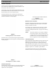
Table Of Contents
- CHAPTER 1 Introduction
- CHAPTER 2 BTR-800 Base Station
- CHAPTER 3 TR-800 Beltpack
- CHAPTER 4 TR-825 Beltpack
- CHAPTER 5 Initial Equipment Setup
- Unpacking
- Antenna Connection
- Antenna Polarization
- Distance between Antennas
- Antenna Placement
- Improving Reception and Increasing Range
- Base Station Set-up
- Location
- Power Connection
- Transmit Switches
- Internal Transmit Switches
- Intercom Switch
- Intercom Interface
- Dual Listen Functionality
- Auxiliary Input/Output
- Internal Auxiliary Input Routing Switch
- Stage Announce / Relay Contacts
- Base Station Link
- Beltpack Setup
- Antenna Connection
- Transmit Mode
- Headset Connection
- CHAPTER 6 Pre-Walk-Thru Checklist
- CHAPTER 7 System Operation
- Frequency Plan Overview
- Factory-Defined Groups
- User-Programmable Groups
- System Quick Start
- Base Station Operation
- Power
- Local Headset
- Portable Station Connect
- Intercom A and B
- Auxiliary
- Display Contrast
- BTR-800 Menu Structure
- Main Screen Flowchart
- Power-Up Screen
- Operating Screen
- Beltpack Activity Code Definitions
- Group/Channel Select
- Group/Frequency Select
- Frequency Edit (User-Programmed Groups Only)
- ClearScan™
- Special Key Sequences
- Lockout
- Copy
- 1st Use Default
- Factory Default
- Beltpack Operation
- On/Off and Volume Control
- Battery Check
- Talk Button
- Microphone Gain
- Audio Channel Select Button
- Stage Announce (SA)
- Wireless Talk Around (WTA)
- TR-800 Menu Structure
- Beltpack Menu Structure
- Power-Up Screens
- Group/Channel Screen
- Transmit Screen
- Receive 1 Screen
- Receive 2 Screen
- ClearScan™
- Stage Announce Enable/Disable
- Wireless Talk Around Enable/Disable
- Audio Channel A or B Disable/Enable
- Talk Button Latch on/Latch off
- Special Key Sequences
- Lockout
- 1st Use Default
- Factory Default
- TR-825 Menu Structure
- CHAPTER 8 System Walk-Thru
- CHAPTER 9 Troubleshooting
- CHAPTER 10 Tech Tips
- CHAPTER 11 Battery Information
- CHAPTER 12 Intercom Systems Specifications
- CHAPTER 13 Accessories and Replacement Parts
- CHAPTER 14 Certification Information
- CHAPTER 15 Three Band Base Stations

18 TR-825 Beltpack BTR-800, TR-800, TR-825
1. [MENU] and [SET] buttons – Used to select menus and
set options on the LCD.
2. LCD (Liquid Crystal Display)
3. [UP] and [DOWN] buttons – Used to select beltpack
options on the LCD.
4. Microphone Gain – Adjusts the headset’s microphone
gain. Adjust so that the BAT/OM LED will flash at the
beginning of most words at normal speech levels.
5. Push-to-Talk/Push-to-Transmit Switch –
Push-to-Talk (PT TALK) - The transmitter is always on. No
audio sen
t unless the talk switch, WTA, or SA button
pressed. Recommended position.
Push-to-Transmit (PT TX) –The transmitter and audio path
are of
f except when the talk swi
tch, WTA, or SA button is
pressed.
6. Headset Connector – Male XLR connector or female XLR
connector. A dynamic or electret headset microphone is
automatically detected by the beltpack and a bias voltage
supplied, if needed. Four-pin units are monaural. Five pin
units have a software setup which ground or opens pin 3.
Single-sided 5-pin headsets will only receive A or B, depending
on how headphone is wired. These headsets must have the
beltpack set for [Ab SEP]
7. Battery Latch – Press down to enable the battery pack to
be released. While the latch is held down, slide the battery
pack about 1/8-inch back, toward the latch, until it stops.
Then lift out.
8. Receive Antenna – Screw type 1/4-wave replaceable
antenna. The color dot on the screw end of the antenna must
match color dot on antenna receptacle.
9. Transmit Antenna – Screw type 1/4-wave replaceable
antenna. The color dot on the screw end of the antenna must
match color dot on antenna receptacle.
FIGURE 8.
TR-825 Rear Panel/Connector/Antennas
Male Connector
Female Connector
FIGURE 9.
Headset Jack Wiring