
Operating Instructions


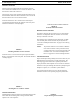
Table Of Contents
- CHAPTER 1 Introduction
- CHAPTER 2 BTR-800 Base Station
- CHAPTER 3 TR-800 Beltpack
- CHAPTER 4 TR-825 Beltpack
- CHAPTER 5 Initial Equipment Setup
- Unpacking
- Antenna Connection
- Antenna Polarization
- Distance between Antennas
- Antenna Placement
- Improving Reception and Increasing Range
- Base Station Set-up
- Location
- Power Connection
- Transmit Switches
- Internal Transmit Switches
- Intercom Switch
- Intercom Interface
- Dual Listen Functionality
- Auxiliary Input/Output
- Internal Auxiliary Input Routing Switch
- Stage Announce / Relay Contacts
- Base Station Link
- Beltpack Setup
- Antenna Connection
- Transmit Mode
- Headset Connection
- CHAPTER 6 Pre-Walk-Thru Checklist
- CHAPTER 7 System Operation
- Frequency Plan Overview
- Factory-Defined Groups
- User-Programmable Groups
- System Quick Start
- Base Station Operation
- Power
- Local Headset
- Portable Station Connect
- Intercom A and B
- Auxiliary
- Display Contrast
- BTR-800 Menu Structure
- Main Screen Flowchart
- Power-Up Screen
- Operating Screen
- Beltpack Activity Code Definitions
- Group/Channel Select
- Group/Frequency Select
- Frequency Edit (User-Programmed Groups Only)
- ClearScan™
- Special Key Sequences
- Lockout
- Copy
- 1st Use Default
- Factory Default
- Beltpack Operation
- On/Off and Volume Control
- Battery Check
- Talk Button
- Microphone Gain
- Audio Channel Select Button
- Stage Announce (SA)
- Wireless Talk Around (WTA)
- TR-800 Menu Structure
- Beltpack Menu Structure
- Power-Up Screens
- Group/Channel Screen
- Transmit Screen
- Receive 1 Screen
- Receive 2 Screen
- ClearScan™
- Stage Announce Enable/Disable
- Wireless Talk Around Enable/Disable
- Audio Channel A or B Disable/Enable
- Talk Button Latch on/Latch off
- Special Key Sequences
- Lockout
- 1st Use Default
- Factory Default
- TR-825 Menu Structure
- CHAPTER 8 System Walk-Thru
- CHAPTER 9 Troubleshooting
- CHAPTER 10 Tech Tips
- CHAPTER 11 Battery Information
- CHAPTER 12 Intercom Systems Specifications
- CHAPTER 13 Accessories and Replacement Parts
- CHAPTER 14 Certification Information
- CHAPTER 15 Three Band Base Stations

22 Initial Equipment Setup BTR-800, TR-800, TR-825
Antenna Connection
The base station is supplied with the two antennas. One 1/2-
wave antenna for Transmit and one 1/2-wave for Receive. The
antennas have TNC male connectors.
The frequency range of the antennas should match the receiver
and transmitter of the base s
tation. Match the color code on the
antenna with the color code on the base station.
Attach the transmit 1/2-wave antenna to the antenna input
receptacle labeled Transmit on the right side of the rear panel.
The antenna should be vertically aligned.
Attach the receive 1/2-wave antenna input receptacle labeled
Receive on the left side of the rear panel. The antenna should be
vertically aligned.
Antenna Polarization
The RTS Wireless Intercom System is Vertically Polarized. This
means both the transmitting and receiving antennas should
operate in the vertical position.
Distance between Antennas
The distance between the base station’s receive and transmit
antennas is not adjustable when the antennas are connected
directly on the back of the unit.
The antennas can be remoted for
better signal path. An RTS
coax assembly with remote antennas may be required. See
“Accessories and Replacement Parts” on page 83 for ordering
information.
NOTE: If yo
ur base station is to be located in a shielded
rack mount enclosure or other poor RF location,
you must remove the 1/2-wave antennas with coax
assemblies. See “Accessories and Replacement
Parts” on page 83 for remote mounting hardware.
Antenna Placement
Proper antenna placement probably has the most effect on your
RTS Wireless Intercom System’s overall performance. The
following suggestions will result in optimum performance.
Proper placement of the beltpack can be critical. The antennas
should be in the open. Bending the antennas up and placing the
beltpack in a pocket, etc., will reduce system distance.
It is suggested that the unit be worn on the belt with both
antenna’s vertical for best operating range and performance.
FIGURE 10.
Attaching Transmit 1/2-Wave Antenna
FIGURE 11.
Attaching Receive 1/2-Wave Antenna
ANTENNAS SHOULD BE VERTICAL
FIGURE 12.
Vertically Polarized Antennas
FIGURE 13.
Proper Dressing of the Antennas