
Operating Instructions
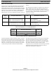
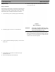
Table Of Contents
- CHAPTER 1 Introduction
- CHAPTER 2 BTR-800 Base Station
- CHAPTER 3 TR-800 Beltpack
- CHAPTER 4 TR-825 Beltpack
- CHAPTER 5 Initial Equipment Setup
- Unpacking
- Antenna Connection
- Antenna Polarization
- Distance between Antennas
- Antenna Placement
- Improving Reception and Increasing Range
- Base Station Set-up
- Location
- Power Connection
- Transmit Switches
- Internal Transmit Switches
- Intercom Switch
- Intercom Interface
- Dual Listen Functionality
- Auxiliary Input/Output
- Internal Auxiliary Input Routing Switch
- Stage Announce / Relay Contacts
- Base Station Link
- Beltpack Setup
- Antenna Connection
- Transmit Mode
- Headset Connection
- CHAPTER 6 Pre-Walk-Thru Checklist
- CHAPTER 7 System Operation
- Frequency Plan Overview
- Factory-Defined Groups
- User-Programmable Groups
- System Quick Start
- Base Station Operation
- Power
- Local Headset
- Portable Station Connect
- Intercom A and B
- Auxiliary
- Display Contrast
- BTR-800 Menu Structure
- Main Screen Flowchart
- Power-Up Screen
- Operating Screen
- Beltpack Activity Code Definitions
- Group/Channel Select
- Group/Frequency Select
- Frequency Edit (User-Programmed Groups Only)
- ClearScan™
- Special Key Sequences
- Lockout
- Copy
- 1st Use Default
- Factory Default
- Beltpack Operation
- On/Off and Volume Control
- Battery Check
- Talk Button
- Microphone Gain
- Audio Channel Select Button
- Stage Announce (SA)
- Wireless Talk Around (WTA)
- TR-800 Menu Structure
- Beltpack Menu Structure
- Power-Up Screens
- Group/Channel Screen
- Transmit Screen
- Receive 1 Screen
- Receive 2 Screen
- ClearScan™
- Stage Announce Enable/Disable
- Wireless Talk Around Enable/Disable
- Audio Channel A or B Disable/Enable
- Talk Button Latch on/Latch off
- Special Key Sequences
- Lockout
- 1st Use Default
- Factory Default
- TR-825 Menu Structure
- CHAPTER 8 System Walk-Thru
- CHAPTER 9 Troubleshooting
- CHAPTER 10 Tech Tips
- CHAPTER 11 Battery Information
- CHAPTER 12 Intercom Systems Specifications
- CHAPTER 13 Accessories and Replacement Parts
- CHAPTER 14 Certification Information
- CHAPTER 15 Three Band Base Stations

28 Initial Equipment Setup BTR-800, TR-800, TR-825
Dual Listen Functionality
The base station’s main audio board has the option of placing
additional parts to enable dual listen. Dual listen allows the
mixing of the intercom channels. The mixing will occur locally,
within the base station, and is only heard on that base station’s
beltpacks. The user will have the ability to enable/disable the
mix of I/C A into I/C B or vise versa. If you have TR-825
beltpacks, there is no need to install this base option. The level
of the mix can be controlled at the TR-825 via the two volume
controls.
They will also have the ability to cont
rol the level of the mix (-
4dB to -24dB down from the main channel). Removing two
surface mount resistors and installing two SPDT switches and
two potentiometer enables dual listen. The parts to be installed
are shown in Table 1. The two resistors on the bard to be
removed are in Table 2.
The listed manufactures and part numbers in Table 1 are those
that the audio board was laid out for and thus the hole pattern
used. Several of these parts may be found at Digi-Key and other
distributors. Trim the leads on the parts so they cannot hit the
metal case. Locations to place these components are provided
on audio board part number 750608 and ASY000108000.
The audio board part number is located on the lower left hand
side of the board if facing the front of the unit. The location
where the components can be installed are on the upper right
hand side of the board. See Figure 22 for the locations. Board
part number 750541does not have locations to place
components, however, modification documents may be obtained
from Bosch Security Systems, Inc. for those who wish to
modify older audio boards for dual listen.
Board
Designator
Description and Function Value Manufacturers, Part No.
VR5, VR6 Potentiometers
VR5 = Controls I/C A into I/C B Mix
VR6 = Controls I/C B into I/C A Mix
20kΩ –25kΩ Bourns, 3309P-1-203
CTS, U262R253B
Piher PT10LV10-203A2020
S6, S7 Switches
S6 = Enable/Disable I/C A into I/C B Mix
S7 = Enable/Disable I/C B into I/C A Mix
SPDT E-Switch, 500ASSP1M2RE
E-Switch, EG1218
AlcoswitchTSS11DGPC
TABLE 1.
Parts to be installed by User to Enable Dual Listen
Board
Designator
Description and Function Value
R295 Resistor, Default if mix components not installed 10k
R296 Resistor, Default if mix components not installed 10k
TABLE 2.
Parts to be Removed by User to Enable Dual Listen
FIGURE 22.
Audio Board Part Number and Dual Listen Component Locations