
Operating Instructions
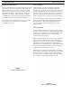

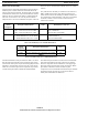
Table Of Contents
- CHAPTER 1 Introduction
- CHAPTER 2 BTR-800 Base Station
- CHAPTER 3 TR-800 Beltpack
- CHAPTER 4 TR-825 Beltpack
- CHAPTER 5 Initial Equipment Setup
- Unpacking
- Antenna Connection
- Antenna Polarization
- Distance between Antennas
- Antenna Placement
- Improving Reception and Increasing Range
- Base Station Set-up
- Location
- Power Connection
- Transmit Switches
- Internal Transmit Switches
- Intercom Switch
- Intercom Interface
- Dual Listen Functionality
- Auxiliary Input/Output
- Internal Auxiliary Input Routing Switch
- Stage Announce / Relay Contacts
- Base Station Link
- Beltpack Setup
- Antenna Connection
- Transmit Mode
- Headset Connection
- CHAPTER 6 Pre-Walk-Thru Checklist
- CHAPTER 7 System Operation
- Frequency Plan Overview
- Factory-Defined Groups
- User-Programmable Groups
- System Quick Start
- Base Station Operation
- Power
- Local Headset
- Portable Station Connect
- Intercom A and B
- Auxiliary
- Display Contrast
- BTR-800 Menu Structure
- Main Screen Flowchart
- Power-Up Screen
- Operating Screen
- Beltpack Activity Code Definitions
- Group/Channel Select
- Group/Frequency Select
- Frequency Edit (User-Programmed Groups Only)
- ClearScan™
- Special Key Sequences
- Lockout
- Copy
- 1st Use Default
- Factory Default
- Beltpack Operation
- On/Off and Volume Control
- Battery Check
- Talk Button
- Microphone Gain
- Audio Channel Select Button
- Stage Announce (SA)
- Wireless Talk Around (WTA)
- TR-800 Menu Structure
- Beltpack Menu Structure
- Power-Up Screens
- Group/Channel Screen
- Transmit Screen
- Receive 1 Screen
- Receive 2 Screen
- ClearScan™
- Stage Announce Enable/Disable
- Wireless Talk Around Enable/Disable
- Audio Channel A or B Disable/Enable
- Talk Button Latch on/Latch off
- Special Key Sequences
- Lockout
- 1st Use Default
- Factory Default
- TR-825 Menu Structure
- CHAPTER 8 System Walk-Thru
- CHAPTER 9 Troubleshooting
- CHAPTER 10 Tech Tips
- CHAPTER 11 Battery Information
- CHAPTER 12 Intercom Systems Specifications
- CHAPTER 13 Accessories and Replacement Parts
- CHAPTER 14 Certification Information
- CHAPTER 15 Three Band Base Stations

BTR-800, TR-800, TR-825 Initial Equipment Setup 29
Auxiliary Input/Output
The input and output 3-pin XLR auxiliary connections are for
supplying additional balanced audio into and receiving balanced
audio from the base station. The output auxiliary connection
only interfaces to intercom B. However, there is an internal
switch to control the routing of the input auxiliary audio. See
“Internal Auxiliary Input Routing Switch” on page 29.
The input and output aux
ilia
ry audio is global. This means
the input auxiliary audio is placed on the base local headset,
beltpack(s), headsets, and any wired intercom system
interfaced to the base station. The intercom channel(s) the
input auxiliary audio is placed on depends on the position of the
input routing switch. The output auxiliary audio is also taken
from the intercom B base local headset, beltpack(s), headsets,
and any wired intercom connected to the base station. A
modification document is available from Bosch Security
System, Inc. for those who wish to modify the base station so
that auxiliary input audio is heard only locally; base local
headset and beltpack(s) headsets.
Internal Auxiliary Input Routing Switch
This switch controls the routing of the input auxiliary audio.
This switch has two positions. The B position places auxiliary
input audio onto intercom B only (default from factory). The A
& B position places auxiliary input audio onto intercom A and
B. See Figure 23 for the locations of this internal auxiliary input
routing switch.
FIGURE 23.
Auxiliary Input Routing Switch